

Hey there, fellow DIYers, gearheads, and automotive tech folks – if you’ve ever found yourself tangled in a web of wiring for your car’s lights, horn, or accessory mods, you know how frustrating it can get. I’m [just me, relay supplier here] – been working with 4-Pin Automotive Relays for years, and let’s be real, connecting multiple of these bad boys doesn’t have to feel like solving a rocket science problem. I’ve seen so many people skip this step and end up with blown fuses, dead accessories, or even short circuits, so I wanted to break it down like we’re chatting over a garage coffee.
First off, let’s get clear on what a single 4-Pin Automotive Relay does – because if you mess up the basics, adding more relays will only multiply the headaches. Every standard 12V 4-pin relay has four terminals, right? Let’s call them out by their standard labels to keep this simple: pin 85, pin 86, pin 30, and pin 87. Pin 85 and 86 are the “control circuit” – that’s the low-voltage side that triggers the relay (usually 12V, draws a tiny current, like 50-100mA) – and pins 30 and 87 are the “load circuit” – that’s the high-voltage side that powers your accessory (like 10A for a fog light, 20A for a horn). If you’re still sorting which is which, grab a 4-Pin 12V Automotive Relay from our site – most have a diagram molded right on the plastic case, so no guessing work, which is why this [4-Pin 12V Automotive Relay] is such a workhorse for basic setups.
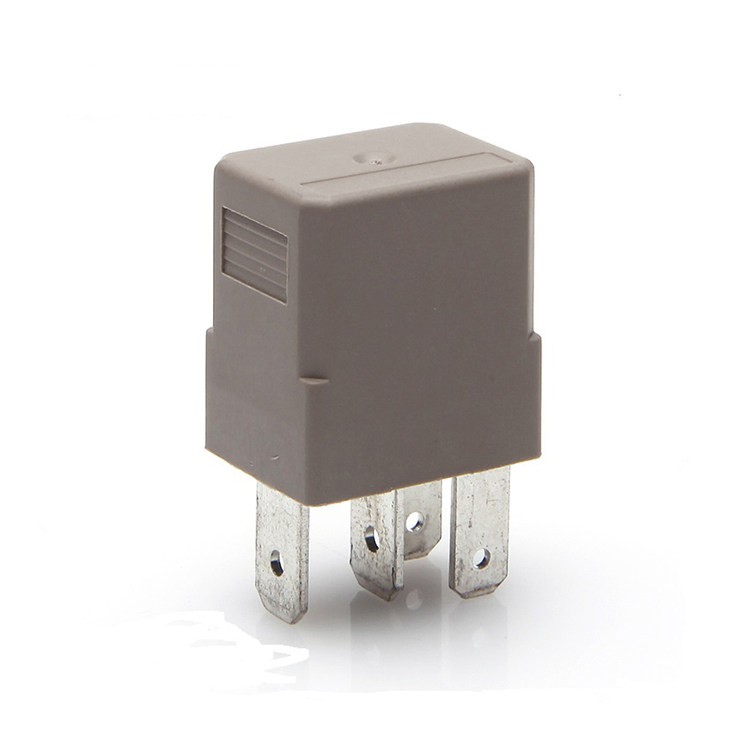

Now, why would you need multiple relays? Let’s say you’re adding fog lights, a backup camera, and a set of LED pod lights to your pickup – each of these needs its own relay because they draw different loads, and you don’t want one faulty accessory taking down all your others. Or maybe you’re wiring a car horn, plus a secondary horn for your off-road build – that’s two Car Horn Relays, each needing a dedicated trigger. Whatever the reason, connecting multiple relays boils down to two parts: the common power feed for the load circuits, and a shared trigger source for the control circuits – but we’re gonna do it the right way to avoid issues.
Let’s start with the most important rule here: never daisy-chain the load circuit power. I see this all the time – someone takes a single power wire, splits it to feed pin 30 on Relay 1, then runs another wire from Relay 1’s pin 87 to Relay 2’s pin 30, and so on. That’s a fast track to a blown fuse because each relay’s load current adds up, and the first wire in the chain can’t handle all the amperage. Instead, we’re using a “common power bus” – this is a 12V power distribution block (you can grab these at any auto parts store, or even repurpose a fuse block if you’re careful) that connects directly to your battery’s positive terminal (always add a main fuse near the battery, like 30A or 50A, to protect the whole setup). Then, every single relay’s pin 30 gets a short wire running straight from this bus. That way, each relay has its own full power feed, no bottlenecks.
Next, the control circuit – this is where people mess up the trigger. If all your relays are triggered by the same source (like your factory headlight switch or a new toggle switch), you can wire the pin 86 terminals all together to a single trigger wire. But wait – make sure that trigger can handle the total current draw of all control circuits. Each 4-Pin Relay’s control circuit is small, like 50mA, so even 10 relays would only be 500mA – which is nothing for a standard automotive switch. Here’s a quick example: if you have two [12V Automotive Relay 4-Pin] units, one for fog lights and one for LED pods, run a single wire from your toggle switch to a terminal block, then split that block to run to pin 86 on both relays. Pin 85 on each relay gets connected to ground – that’s the other side of the control circuit. Easy peasy.
But what if you want some relays to trigger separately? Like, fog lights turn on with the headlights, and LED pods turn on with a separate toggle? Then you just don’t wire the pin 86 terminals together – each gets its own trigger wire. Pin 85 still goes to ground for every one, no exceptions – the control circuit needs a complete loop, so pin 85 is always your ground for that side. Let’s test this with a real use case: a car horn setup. If you want a primary horn and a secondary high-pitch horn, grab two Car Horn Relays. Wire each relay’s pin 30 to the common power bus, pin 85 to a chassis ground (make sure the ground is clean – sand paint off the frame where you attach the wire, or use a ground stud, not just a loose bolt), and pin 86 on both relays to the same horn button. Then pin 87 on each relay connects directly to each horn. Now your horn button triggers both horns at once – that’s a double honk that’ll make sure everyone hears you.
Wait, let’s talk about a common mistake with automatic relays – the [12V 4 Pin Automatic Relay] is a bit different from a standard relay, because it triggers automatically (usually when voltage hits a threshold, like for fuel pumps or cooling fans). If you’re using multiple automatic relays, don’t share their trigger wires – each should have its own voltage-sensing wire. Sharing that would make both relays trigger at the same time, which might not be what you want. Also, automatic relays draw a bit more current when they’re switching, so double-check your power bus can handle that extra draw.
Now, let’s walk through a step-by-step small project to make this concrete. Let’s say you’re wiring 3 accessories: a backup camera (5A), a set of LED rock lights (10A), and a small auxiliary fan (7A). That’s 3 relays, each a 12V 4-pin one. Here’s the play-by-play:
- Grab a 12V 4-pin relay for each accessory – stick to our [12 Volt Car Relay] line for these, they’re rated for up to 20A each, more than enough for this job.
- Run a main power wire (10 gauge is good for small loads, 8 gauge if you go over 20A total) from the battery positive, add a 40A fuse within 6 inches of the battery, then connect that to a power distribution block.
- From the distribution block, run a 14 gauge wire to pin 30 on each of the 3 relays – no daisy-chaining, each relay gets its own short wire from the block.
- For triggers: Let’s say the backup camera triggers when you put the car in reverse, the rock lights trigger with your interior lights, and the fan triggers when the engine is hot. That means 3 separate trigger sources. Run 14 gauge wire from reverse light wiring to pin 86 on the camera relay, from interior light wiring to pin 86 on the rock light relay, and from a coolant temp sensor (or a manual toggle) to pin 86 on the fan relay.
- For grounds: Run a 16 gauge wire from a clean chassis ground to pin 85 on each of the 3 relays. No skimping here – a bad ground will make the relay act flaky, like clicking on and off for no reason.
- Finally, run pin 87 on each relay to its accessory: pin 87 to the camera’s power wire, pin 87 to the rock lights, pin 87 to the fan’s power.
Test time! Turn on each trigger separately – the right accessory should turn on every time. If a relay clicks but the accessory doesn’t, check pin 87 power (maybe a loose wire), or the ground on pin 85 (dirty connection). If nothing happens, check the trigger wire voltage (should be ~12V when active) and the power to pin 30.
Now, a few pro tips from someone who’s wired dozens of these setups: First, label every single wire with a marker, or use different colored wires for each relay – white for pin 30, black for ground, red for triggers, etc. When you’re under the dash or in a tight engine bay, you’ll thank yourself later. Second, don’t skip the fuses for each accessory – each pin 87 should have its own fuse near the relay, rated for the accessory’s current. That way, if one accessory shortens, it only blows its own fuse, not the whole main power. Third, if you’re working with a classic car with old wiring, add relay sockets to each setup – they make swapping a bad relay way easier than rewiring everything.
Wait, can you connect more than 5 relays? Absolutely – just make sure your power distribution block can handle the total current. Let’s do the math: each 12V 4-pin relay’s load circuit is up to 20A, so if you have 10 relays, that’s 200A total – you’ll need a power distribution block rated for at least 250A, and a main wire (2 gauge) that can carry that, plus a big enough fuse near the battery. The control circuits still only draw ~50mA each, so sharing a trigger is fine even for 15 relays.
I know this sounds like a lot, but it’s way simpler than it looks. A lot of people overcomplicate multiple relays, but once you get the hang of the power bus and separate triggers, it’s just repeating the same steps for each relay. If you’re still not sure which relay to grab, or have a custom setup for your project, I’m here to help – we’ve got all the 4-pin relays you need, from standard automotive ones to specific ones like car horn relays, ready to ship. Don’t mess up your project with flaky wiring – reach out to us to get the right parts and talk through your setup.
References
- Automotive Relay Installation Guide, SAE International, 2022
- 12V Automotive Relay Wiring Best Practices, Wiring Harness Manufacturers Association, 2023
- Multiple Relay Power Distribution Standards, National Automotive Technicians Education Foundation (NATEF), 2021