

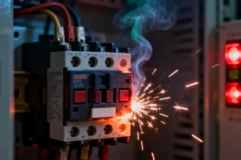
That buzzing sound from a relay isn't just annoying. It's a warning sign. Your circuit is unstable, and a component is about to fail.
The main reason is almost always the same. The relay's electromagnetic coil isn't getting enough stable voltage. It's stuck in a loop, trying to engage but lacking the power to stay in position.
This guide will walk you through fixing this problem. We'll identify the signs of relay chatter first. Then we'll explore the root causes. Finally, we'll provide step-by-step solutions to make your DC circuits stable and reliable again.
Understanding the Signs
Decoding the "Buzz"
Relay chatter shows up through clear audio and electrical symptoms. Recognizing them helps you diagnose correctly.
Audio Symptoms:
A buzzing sound like a small transformer hum.
Rapid, high-frequency clicking or "chattering" noise.
This is very different from the single, clean "click" of a healthy relay switching on or off.
Electrical Symptoms:
Flickering power to connected devices. Lights flicker or motors stutter.
Inconsistent operation of the entire circuit.
Visible arcing across relay contacts. You can sometimes see this in clear-cased relays.
More Than Just Noise
Ignoring relay chatter leads to bigger failures in your system. The consequences go far beyond an irritating sound.
Rapid switching creates intense electrical arcing between the relay's contacts. This arcing wears down the contact material. Eventually, the relay fails permanently.
Erratic power delivery also destabilizes the entire circuit. This affects other sensitive components connected to the same power source.
In critical applications like industrial controls or automotive systems, an unreliable relay can cause complete operational failure. This leads to downtime and potential safety hazards.
The Root Causes
Cause #1: Insufficient Voltage
Relay operation depends on two key voltage specifications: "pull-in" and "drop-out" voltage. Pull-in voltage is the minimum needed to fully close the relay's contacts.
Drop-out voltage is the level below which the coil can't hold contacts closed. They release when voltage drops this low. Relay buzzing symptoms occur when coil voltage hovers between these two thresholds.
This usually happens because of excessive voltage drop in the circuit.
Undersized Wires: Wires that are too thin for the required current and distance act like resistors. They cause significant voltage loss.
Long Wire Runs: Even with correct wire size, voltage drop happens over distance. The longer the path from power supply to relay, the lower the voltage at arrival.
Poor Connections: Every connection can create resistance. Cold solder joints, loose terminals, or corroded contacts all contribute to voltage drop relay failure.
Failing Power Supply: The power source itself may be the problem. It can't maintain stable output voltage under load. This leads directly to relay failure.
Cause #2: Unstable Supply
Power supply specifications matter just as much as relay specifications. A mismatch or poor-quality supply commonly causes chatter.
If the power supply can't provide enough current for the entire circuit, its output voltage will "sag" when components draw power. This sag can easily push voltage below the relay's pull-in threshold.
A poorly filtered DC power supply has significant "ripple." This is leftover AC component on top of DC voltage. If voltage ripple troughs dip below the relay's drop-out voltage, the relay rapidly switches on and off, creating buzz. A stable power supply for relays is essential.
When a relay shares power with a high-current device like a motor, problems arise. The massive startup current drawn by a motor causes momentary but severe voltage dip across the entire power rail. This makes nearby relays chatter or release.
Cause #3: The Load's "Kick"
The type of load being switched can itself cause the problem. This especially affects inductive loads like motors, solenoids, or other relay coils.
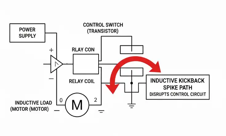
When a relay cuts power to an inductive load, the collapsing magnetic field induces a large, reverse-polarity voltage spike. This is called inductive kickback or back EMF.
This high-voltage spike doesn't just disappear. It travels back through wiring, creating electromagnetic interference (EMI). This noise disrupts the main power rail or interferes with the control signal driving the relay. The coil's voltage becomes unstable, leading to chatter.
A simple diagram would show a power supply, control switch (like a transistor), relay coil, and inductive load (like a motor). When the relay opens, an arrow points from the motor back toward relay contacts, showing the inductive kickback spike path that disrupts the control circuit.
Systematic Troubleshooting
Safety and Tools
Before diagnosing, prioritize safety. Always turn off power before touching or modifying components.
For effective troubleshooting, you need essential tools. A quality digital multimeter (DMM) is required. You also need your specific relay's datasheet to know its nominal, pull-in, and drop-out voltage ratings. For advanced diagnostics, an oscilloscope helps visualize voltage ripple and transients.
The Diagnostic Flow
This is the exact process we follow to quickly and accurately diagnose relay issues. It saves time and prevents guesswork through logical, measurement-based approach.
First, observe the symptoms. When does chatter happen? Is it immediate at power-up, or only when another device like a motor activates? Initial observation provides valuable clues.
The most important diagnostic step is measuring voltage directly at the coil. With the circuit powered and relay supposed to be engaged, place DMM probes directly across the relay's coil terminals (+ and -).
Compare your measurement with the relay's datasheet. Is measured voltage significantly lower than the relay's nominal voltage? Is it hovering near the specified drop-out voltage? If yes, you've confirmed a voltage supply or voltage drop issue.
For example, a 12VDC relay might have 9V pull-in voltage and 2.5V drop-out voltage. If you measure 3V at the coil, it will almost certainly chatter as it struggles to hold state.
Next, test the power supply itself. Keep the circuit running and measure voltage at the power supply's output terminals. If this voltage is also low and unstable, the power supply is either failing or undersized for the load. If supply voltage is stable and correct, the drop happens in wiring or connections between it and the relay.
Finally, isolate the load. Carefully disconnect the load (like a motor) from the relay's switched contacts (COM and NO/NC terminals). Power the circuit again. If the relay now energizes with a solid click and chattering stops, the problem is almost certainly inductive kickback protection from the load you disconnected.
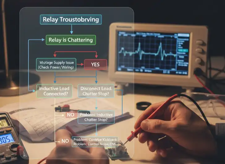
This diagnostic process works like a decision tree:
Start: "Relay is Chattering"
-> Measure Voltage at Coil.
-> Is Voltage < Pull-in Voltage?
YES -> You have a voltage supply issue. Investigate power supply stability under load and check for voltage drop in wiring and connections.
NO -> The coil has enough voltage. The issue is likely external. Is an inductive load connected?
YES -> Disconnect the load. Does chatter stop?
YES -> The problem is inductive kickback from the load.
NO -> The problem is likely control signal noise or severe EMI from another source.
Proven Solutions
Solution #1: Fortifying the Path
This solution directly addresses voltage drop issues and minor power supply instability at the coil.
Strengthen your power delivery foundation. Use thicker gauge wires (lower AWG number) for power and ground lines running to the relay where possible. Shorten wire runs to minimize resistance. Examine all connections critically. Re-solder suspicious joints and securely tighten all screw terminals.
A highly effective and common fix is adding a decoupling capacitor. This capacitor acts as a tiny, local power reservoir right at the relay coil. It smooths out small, fast voltage dips.
To implement this, place a 10µF to 100µF electrolytic capacitor directly across the relay coil's positive and negative terminals. Also add a small 0.1µF ceramic capacitor in parallel with the electrolytic one. The larger capacitor provides bulk energy to ride through voltage sags. The smaller ceramic capacitor filters out high-frequency noise.
A simple schematic would show the relay coil with electrolytic and ceramic capacitors connected in parallel across its terminals, ensuring correct polarity for the electrolytic capacitor.
Solution #2: Taming Kickback
If your diagnosis pointed to inductive kickback, you must implement a protection circuit to absorb the damaging voltage spike.
The classic and most common solution in DC circuits is the flyback diode. This simple component gives inductive current a safe path to circulate and dissipate when the relay opens. This prevents the voltage spike.
To implement this, place a diode (1N4001 is a common choice) in reverse bias across the inductive load's terminals. The diode's cathode (stripe side) connects to the positive side of the load. The anode connects to the negative side. When the relay cuts power, the reverse voltage spike forward-biases the diode, creating a safe current loop.
A clear schematic would show the relay switching a motor. The flyback diode would be placed directly across the motor's + and - terminals, with the stripe facing the + terminal. While the flyback diode is excellent, other methods exist for specific applications.
|
Method |
How It Works |
Pros |
Cons |
Best For |
|
Flyback Diode |
Provides a path for inductive current to circulate and safely dissipate. |
Simple, cheap, very effective. |
Can slightly increase the turn-off time of the load. |
Most general-purpose DC inductive loads (motors, solenoids, other relays). |
|
RC Snubber |
Absorbs the spike's energy in a resistor and capacitor network placed across the contacts. |
Faster turn-off than a diode, works on both AC and DC circuits. |
More complex to calculate component values, generates some heat. |
AC circuits, or DC applications where fast de-energization is critical. |
|
TVS/Zener Diode |
"Clamps" the voltage spike to a predefined, safe level by conducting once that voltage is exceeded. |
Very fast response time, precise voltage clamping. |
More expensive, may have lower energy handling capacity than a flyback setup. |
Protecting highly sensitive control electronics from fast electrical transients. |
Solution #3: Upgrading Power
Sometimes, the only real solution is addressing the power source itself.
Choose a power supply with current rating at least 25-50% higher than the total calculated maximum current draw of your entire circuit. This overhead ensures the supply isn't strained and can handle startup currents without voltage sagging.
When selecting a supply, check its datasheet for good regulation specifications. Look for "load regulation" of 2% or less, and low "ripple & noise" figures (typically measured in millivolts). A well-regulated supply maintains stable output voltage regardless of load.
For critical or noisy applications, best practice is completely isolating your control circuits. Use a separate, dedicated, stable power supply for relays and other sensitive logic. This protects them from voltage fluctuations caused by high-current components like motors.
A Note on Bouncing
What is Contact Bouncing?
It's important to distinguish coil chatter from a related but different phenomenon: contact bouncing issues. This is a purely mechanical issue.
Think of dropping a metal ball onto a hard surface. It will bounce a few times before settling. Similarly, when relay contacts are driven together, they physically bounce off each other for a few milliseconds before making solid, continuous contact.
This microscopic bouncing happens during every normal switching event, whether the relay is healthy or not. Coil chatter is an electrical problem that forces the entire relay mechanism to rapidly switch on and off hundreds of times per second.
Why It Matters
The distinction is critical because solutions are entirely different and apply to different circuit parts.
Relay chatter is a coil and control circuit problem. It's fixed on the input side by stabilizing the coil's voltage, as we've discussed.
Normal contact bouncing affects the device reading the relay's output, such as a microcontroller. It's handled on the output side, typically with software "debouncing" algorithms or simple hardware RC filter on the microcontroller's input pin to ignore rapid, brief pulses.
Conclusion: Building Robust Circuits
Relay chatter is a clear warning sign that should never be ignored. By understanding its root causes, you can move from frustration to confident diagnosis and permanent solution.
The golden rule of relay operation is simple: stable coil voltage is the key to silent, reliable relay operation. Your goal is ensuring voltage at the coil consistently stays above the pull-in threshold during operation and cleanly drops to zero when turned off.
Remember the diagnostic journey: Observe symptoms, measure voltage at critical points, isolate components to pinpoint the culprit, then implement the correct fix.
Fix voltage drop with proper wiring, secure connections, and adequate power supply.
Add a decoupling capacitor directly at the coil for essential local voltage stability.
Use a flyback diode or other snubber circuit to tame inductive loads in your system.
By applying these principles, you move beyond simply fixing a problem. You gain skills to design and build robust, reliable, professional-quality electronic circuits that function exactly as intended.
Functions of Time Delay Relays in Industrial Automation Guide 2025
Selecting relays for LED lighting control systems: 2025 Engineer Guide
SSR vs EMR in HVAC: Difference between Solid State & Electromechanical
Definition of pins 85, 86, 30, and 87 for automotive relays - 2025 Guide