


Read a relay datasheet in a fixed order before comparing price: identify the exact orderable part, confirm the contact diagram and terminals, match the coil to the real control supply, and then match the contacts to the actual AC or DC load, inrush, switching frequency, and required electrical life. Finish by checking temperature, insulation, mounting, approvals, document revision, and every footnote behind the headline ratings.
The buyer's rule
Do not ask only, "Is this a 24 V, 10 A relay?" Ask, "Can this exact part number reliably operate from our control supply and make, carry, and break our exact load at the highest voltage, temperature, and cycle count?" A useful supplier answer should point to an exact rating row, graph, drawing, certificate, or application test.
A relay datasheet is a controlled description of a component under stated conditions. It is not permission to combine every maximum value on the page. A 10 A resistive AC rating does not automatically cover a 10 A motor, solenoid, capacitor-input supply, or DC load. Likewise, a nominal 24 VDC coil can still chatter if voltage at the coil terminals falls below the operate requirement during startup.
This guide is written for OEM engineers, panel builders, sourcing teams, distributors, quality personnel, and maintenance planners. It supports screening and supplier communication; it does not replace the exact manufacturer's instructions, applicable equipment standards, qualified electrical work, or validation in the finished product.
The Eight Checks to Complete Before Buying
- Exact identity: full order code, datasheet revision, lifecycle status, package, terminals, sealing, and special suffixes.
- Contact circuit: Form A, B, or C; number of poles; normal state; terminal view; and any series-contact or polarity requirement.
- Coil operation: AC or DC, nominal voltage, operate and release limits, power/current, driver, suppression, and temperature margin.
- Contact capability: rated load, maximum switching limits, carry current, minimum load, contact material, and initial contact resistance.
- Real load: AC or DC waveform, running current, inrush, power factor or time constant, make/break duty, and switching frequency.
- Endurance and timing: electrical life, mechanical life, operate/release time, bounce, and the test conditions for each value.
- Installation envelope: ambient temperature, derating, humidity, condensation, vibration, socket, PCB, terminals, and insulation coordination.
- Evidence and control: exact certificate scope, conditions of acceptability, material declarations, traceability, and product-change notification.

The coil and contacts belong to different sides of the relay specification, but their behavior affects one another through timing and temperature. Image: David Boettcher, Wikimedia Commons, released to the public domain.
First Learn the Language of a Datasheet
Not every number has the same status. A responsible comparison distinguishes a rating or limit from a typical characteristic, an initial value, a curve, and a test result. Panasonic explicitly notes that catalog reference data based on sample evaluation or measurement is not necessarily a guaranteed value. Read the heading, symbol, tolerance, test method, temperature, and footnotes before copying a number into a BOM comparison.
| Datasheet wording | What it usually means | Buyer action |
|---|---|---|
| Rated / nominal | The intended reference condition or named product variant | Read the complete condition; nominal does not mean any nearby value is acceptable |
| Maximum / minimum | A boundary defined under stated conditions | Do not combine separate maxima unless the table or curve permits that operating point |
| Typical / reference | Representative behavior, often based on samples | Use for design insight, not as a guaranteed production limit unless stated |
| Initial | Measured before endurance or environmental exposure | Do not assume the same value after aging, contamination, or contact wear |
| Curve | Relationship observed or specified over selected test points | Read axes, units, load type, contact form, temperature, and whether interpolation is allowed |
| Test condition | The environment and circuit used to produce a value | List every difference between the test and your application |
Common mistake: Copying a number without its qualifier. "100,000 operations," "10 A," "1,500 VAC," and "85°C" are incomplete specifications until the load, nodes, duration, switching rate, contact arrangement, and derating conditions are known.
Step 1: Lock Down the Exact Orderable Part Number
Compare exact part numbers, not relay families. A suffix can change coil voltage, contact form, terminal style, enclosure construction, contact material, sensitivity, latching function, approval, packaging, or manufacturing option. Two distributor listings with the same family name can therefore describe different electrical and production configurations.
Start at the ordering-code table and decode every character. Cross-check the order code against the dimension drawing, terminal map, coil table, rating table, and certificate. If any suffix remains unexplained, the part is not ready for BOM approval.
| Identity field | Record this | Why it matters |
|---|---|---|
| Full manufacturer code | Every prefix, base code, coil code, contact code, and suffix | Prevents an incomplete marketplace description from becoming the BOM definition |
| Document identity | Datasheet number, revision, publication date, and source URL | Creates a traceable engineering baseline for later changes |
| Lifecycle status | Active, NRND, last-time-buy, obsolete, or supplier confirmation | Avoids qualifying a part that cannot support the product lifetime |
| Mechanical option | PCB, plug-in, socket, tab, screw, tray, tube, or reel version | Controls footprint, mating hardware, processing, and sometimes rating |
| Special construction | Sealed, flux-resistant, latching, polarized, sensitive coil, or approval option | Can change assembly compatibility, drive behavior, environment, and evidence |
Control habit: save the approved datasheet and drawing with the BOM record, map the distributor SKU to the full manufacturer code, retain an approved sample, and require a product-change-notification process for production programs.
Step 2: Read the Contact Diagram Before the Ampere Rating
The diagram tells you what the relay actually does when its coil is de-energized and energized. Form A is normally open (NO), Form B is normally closed (NC), and Form C is changeover. Count the poles, identify the common terminal, and confirm whether the drawing is a top view, bottom view, or terminal-side view.

Relay symbols help identify coils, normally open contacts, normally closed contacts, and multi-pole arrangements. Image: Moxfyre, based on public-domain source symbols, Wikimedia Commons, released to the public domain.
| Contact term | De-energized state | Design question |
|---|---|---|
| Form A / NO / SPST-NO | Open | Should loss of coil power turn the load off? |
| Form B / NC / SPST-NC | Closed | What happens if the control supply or coil fails? |
| Form C / SPDT / changeover | Common connected to NC | Are both paths rated for the intended loads and timing? |
| Multiple poles | Each pole shown in its normal state | May different poles switch different circuits, voltages, or phases? |
| Series contacts | Depends on the stated topology | Does the manufacturer explicitly rate this series connection for DC? |
Do not parallel ordinary contacts to "double" the current. TE Connectivity cautions that contacts do not necessarily make and break simultaneously, and the balance is not maintained throughout life. Also avoid assuming that a normal Form C device provides a guaranteed break-before-make interval for a safety or direction interlock. Use the exact timing and topology evidence required by the circuit.
Step 3: Read Coil Data as a Control-Power Specification
Nominal coil voltage identifies the coil version; it does not describe the entire operating window. Read it together with operate voltage, release voltage, coil resistance or impedance, rated current or power, maximum allowable voltage, temperature behavior, polarity, duty, and the control driver's capabilities.
| Coil field | Correct interpretation | Application check |
|---|---|---|
| Nominal voltage | The intended coil version, such as 24 VDC | Match AC/DC, frequency, polarity, waveform, and source tolerance |
| Operate / pickup voltage | Voltage at or below which the relay must operate under stated initial conditions | Ensure worst-case voltage at the coil terminals has adequate margin |
| Release / dropout voltage | Voltage at or above which the relay must return as voltage decreases | Confirm the driver and suppression allow release when required |
| Coil power / current | Input burden at the stated rated condition | Size the driver and supply for simultaneous relays and hot operation |
| Maximum allowable voltage | An upper limit that may depend on temperature and duty | Do not treat it as a recommended continuous drive voltage |
| Operate / release time | Delay under stated voltage, load, temperature, and test circuit | Include bounce, suppression, driver delay, and variation in the timing budget |
Measure voltage at the coil terminals
Supply wiring, transistor voltage drop, PLC leakage, connector resistance, and another load's inrush can reduce the voltage that reaches the coil. Measure or model the worst cold and hot conditions at the relay terminals. Chatter or incomplete armature seating can sharply reduce contact life even though the power supply itself reads the correct nominal voltage.
Use coil equations only where they apply
For a simple DC coil with resistance R at a specified temperature, steady-state current can be approximated by I = V / R, and coil power by P = V² / R. These equations do not directly model an AC coil, an electronic economizer, PWM drive, a latching pulse, or resistance change with temperature. Use the manufacturer's coil table and the actual drive circuit for the final calculation.
Suppression is also part of coil selection. A flyback diode can protect a DC driver but slow release. That may change interlock timing and contact arcing. Confirm polarity, clamp method, release-time effect, and whether suppression is built into the relay or socket.
Step 4: Separate Rated Load, Maximum Limits, Carry Current, and Minimum Load
The contact table contains several different boundaries. Panasonic defines maximum switching capacity as an interrelationship between maximum switching power, voltage, and current. Therefore, never multiply the maximum voltage by the maximum current and assume that the resulting point is permitted.
| Contact field | What it answers | What it does not prove |
|---|---|---|
| Rated load | A stated voltage, current, and load condition, often tied to life | Performance with another waveform, load type, temperature, or cycle rate |
| Maximum switching voltage | Upper switching-voltage boundary under stated conditions | An insulation or working-voltage rating for the whole assembly |
| Maximum switching current | Upper make/break current boundary under stated conditions | Continuous carry, inrush, motor, or fault-current capability |
| Carry current | Current through already-closed contacts within a thermal limit | The ability to close or open that current repeatedly |
| Minimum load | A guide to low-level switching under stated conditions | Guaranteed dry-circuit performance under every environment and life stage |
| Contact resistance | Resistance measured by a defined method, often at initial condition | Complete path loss after years of switching, including socket and PCB |
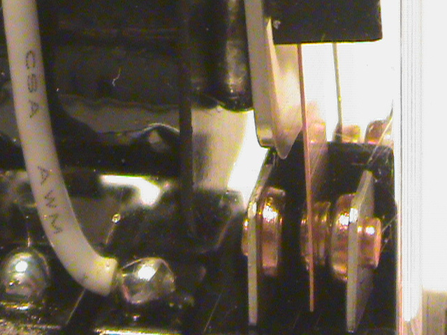
Contact performance depends on material, geometry, load waveform, arcing, contamination, and accumulated wear-not current alone. Image: Pineywoodsdavid, Wikimedia Commons, CC BY-SA 3.0.
Turn one "10 A" label into four questions: Can the relay carry 10 A in our enclosure? Can it close 10 A into our load? Can it open 10 A at our voltage and waveform? How many times can it do so? The answers may come from different tables and curves.
Step 5: Match AC, DC, Inrush, and the Real Load Type
Contact life is controlled by what the relay makes and breaks. AC current crosses zero every cycle, which can help extinguish an arc; DC interruption can be more demanding. A 250 VAC rating cannot be transferred to a battery, solenoid, DC bus, or other DC circuit unless the exact datasheet gives applicable DC evidence.
Steady-state current is only one part of the load. Measure or obtain the peak inrush, duration, repetition, power factor or inductive time constant, DC polarity where relevant, and fault energy. TE advises measuring inrush before specifying the relay and notes that worst-case circuit conditions-not steady state-determine the required rating.
| Load type | Contact stress | Evidence to seek |
|---|---|---|
| Resistive heater | Usually predictable current, but continuous heating matters | Resistive rating, life, ambient derating, terminal temperature |
| Motor | High starting or locked-rotor current and inductive opening | Motor/load-category rating, start profile, electrical endurance |
| Solenoid or valve | Inductive energy sustains the opening arc | DC/AC inductive rating, suppression, time constant, release test |
| Lamp or LED driver | Cold filament or input capacitor can create high inrush | Lamp/inrush rating or instrumented waveform test |
| Transformer | Phase-dependent magnetizing inrush | Transformer-load evidence and measured worst-case peak |
| Capacitor-input supply | High closing current can cause bounce, pitting, or welding | Capacitive making duty, precharge design, waveform test |
| Battery or DC bus | Sustained DC arc and high available fault energy | Explicit DC make/break rating, topology, polarity, protection coordination |
If the datasheet does not cover the load, do not convert the nearest resistive rating yourself. Define the missing condition, ask the manufacturer for application evidence, and test a representative circuit. The right conclusion may be a different relay, contactor, SSR, inrush-limiting circuit, precharge path, or suppression method.
Step 6: Read Electrical Life, Mechanical Life, and Timing Correctly
Mechanical life is normally the number of unloaded operations under specified conditions. Electrical life is the number of operations while switching a stated load. For buying decisions, the electrical-life value is meaningful only when its voltage, current, AC/DC waveform, load type, switching frequency, coil condition, and ambient temperature resemble the application.
A life curve is not a warranty calendar. It can estimate the effect of voltage and current within its stated test family, but it does not automatically cover motor inrush, inductive suppression, synchronized AC switching, contamination, or a hotter enclosure. If a datasheet gives 100,000 operations, dividing by annual cycles is a planning calculation-not a guaranteed replacement interval.
| Life/timing field | Read with | Common error |
|---|---|---|
| Electrical life | Exact load, voltage, current, frequency, temperature, and failure criterion | Using a resistive result for a motor, solenoid, or capacitive load |
| Mechanical life | Unloaded operation and test frequency | Treating it as loaded field life |
| Operate time | Coil voltage, temperature, contact definition, and driver | Ignoring controller delay and bounce |
| Release time | Suppression circuit, residual voltage, temperature, and load | Assuming the datasheet value still applies with a flyback diode |
| Bounce | Contact/load waveform and receiving circuit | Ignoring repeated inrush or false digital transitions |
Step 7: Check Temperature, Insulation, Terminals, and Environment
A wide operating-temperature range does not mean every coil, contact, and life rating is unchanged across that range. Check current derating, maximum coil voltage, hot-start behavior, adjacent heat sources, contact arrangement, and mounting density. The local ambient inside a cabinet can be much higher than the air entering the equipment.
Keep insulation terms separate. Insulation resistance is measured between defined isolated parts using a stated method. Dielectric strength is a withstand test between defined nodes for a stated voltage and duration. Surge withstand uses a specified impulse waveform. None of these values alone defines the finished PCB's working voltage, creepage, clearance, pollution degree, altitude, connector, enclosure, or protection coordination.
- Environmental construction: confirm whether "sealed," "flux-resistant," or "washable" is defined for the exact variant and manufacturing process.
- Condensation: a "non-condensing" condition requires real enclosure and dew-point control.
- Socket and terminals: the socket, lug, wire, screw torque, PCB copper, and connector may impose a lower current or temperature limit than the relay.
- PCB process: check land pattern, solder profile, cleaning restrictions, terminal stress, and whether a sealed relay needs venting after assembly.
- Vibration and shock: review functional and destructive tests, axes, mounting, socket retention, and the installed harness.
- Contamination: dust, sulfur, silicon vapors, oil mist, and cleaning residue can change contact and insulation behavior.
For power paths, evaluate the complete series resistance: contact, terminal, socket or lug, wire or busbar, and PCB copper. A small resistance increase can generate significant heat because conduction loss rises approximately with I²R. Test temperature rise in the assembled product at the worst credible ambient and load.
Step 8: Read Standards, Marks, and Certificates Without Overclaiming
A catalog logo is not enough. Verify the exact part number and suffix, certification body, standard and edition, ratings, factory or model scope where relevant, certificate status, and conditions of acceptability. Some series pages show marks that apply only to selected coils, contacts, terminals, or constructions.
UL explains that a UL Recognized Component is intended for use within a larger certified end product under defined conditions. It is different from a UL Listed finished product. Those conditions can include enclosure, wiring, temperature, and other limitations. Therefore, component recognition can support an end-product evaluation, but it does not automatically certify the machine, panel, appliance, or field installation.
IEC 61810-1:2015+AMD1:2019 covers general and safety requirements for electromechanical elementary relays within its scope. The IEC also states that when an application creates additional requirements beyond that scope, the relay should be assessed according to the relevant application standards. A safety function, medical device, appliance, machine, PV inverter, battery system, or control panel may therefore require additional component and end-product evidence.
| Evidence item | Verify | Safe conclusion |
|---|---|---|
| UL Recognized Component | Exact configuration, file/category, ratings, and conditions | Can support end-product review when used within its evaluated conditions |
| IEC/EN certificate or report | Standard edition, model scope, exceptions, and current status | Provides component evidence only within the stated scope |
| RoHS/REACH declaration | Supplier, part number, scope, date, and substance statement | Supports material compliance records, not electrical qualification |
| Logo or certificate image | Traceable file/report and online status | A logo alone is insufficient BOM evidence |
| Alternate-source evidence | Differences in ratings, construction, terminals, life, and approvals | Requires engineering and compliance review; not automatically drop-in |
A Practical 10-Minute Datasheet Screening Workflow
- Write the application in one sentence: what must close or open, at what voltage/current, how often, and in what environment?
- Identify the exact variant: full part code, document revision, lifecycle, contacts, coil, package, and terminals.
- Read the diagrams: contact form, poles, terminal numbers, coil terminals, top/bottom view, and required topology.
- Check the coil: source type, nominal voltage, worst-case terminal voltage, operate/release limits, power, heat, driver, and suppression.
- Find the matching contact evidence: AC/DC, voltage, current, load type, inrush, carry/make/break duty, and maximum limits.
- Read loaded life: use the electrical-life row or curve, with its switching rate and temperature-not mechanical life.
- Check the installed envelope: derating, humidity, condensation, vibration, socket, terminals, PCB, and insulation.
- Verify approvals: exact part, current certificate, conditions of acceptability, and end-product pathway.
- List unanswered conditions: for example DC interruption, motor inrush, hot pickup, fault energy, or low-level reliability.
- Escalate and validate: send the completed application data to the supplier and test the assembled circuit before production release.
Stop the comparison when: the full suffix is unknown, the terminal drawing conflicts with the listing, only a resistive rating covers a special load, only mechanical life is published, the certificate cannot be traced to the variant, or the supplier cannot explain which table supports the proposed use.
How to Compare a Proposed Relay Substitute
The same footprint, contact form, nominal coil voltage, and headline current do not establish equivalence. A substitute can change pickup margin, coil power, release timing, contact material, DC breaking ability, electrical life, terminal heat, sealing, insulation, or certificate scope while still fitting the board.
| Comparison area | Compare these fields | Why "same rating" can fail |
|---|---|---|
| Circuit behavior | Form, poles, terminal map, normal state, series/parallel restrictions | The wrong path or fail state cannot be fixed by a current rating |
| Coil behavior | Operate/release, power, temperature, driver, timing, suppression | Both relays may say 24 VDC but load the controller differently |
| Contact performance | AC/DC, load type, make/break, inrush, carry current, life, material | A resistive 10 A value does not prove motor or DC life |
| Mechanical/thermal | Dimensions, terminals, socket, PCB, heat, mounting, process | A matching outline does not prove terminal or enclosure margin |
| Insulation/environment | Defined nodes, withstand, sealing, humidity, vibration, contamination | Similar size does not mean identical isolation or protection |
| Compliance/supply | Certificates, conditions, traceability, PCN, lifecycle, production source | A family logo does not establish end-product acceptance |
"Higher" is not always "better." A higher-power coil may overload the driver. Faster release may change an interlock. A contact material optimized for power can be unreliable for a dry signal. Define the required system behavior first, then decide whether each difference is acceptable, needs testing, or blocks the substitution.
What to Include in a Relay RFQ
An RFQ that says "24 V relay, 10 A" invites an ambiguous quote. Give the supplier the conditions needed to connect your circuit to a documented model and ask them to state every deviation.
| RFQ field | Information to provide | Evidence to request |
|---|---|---|
| Function and load | On/off, transfer, motor, valve, heater, PSU, battery, feedback, or interlock | Exact rating row or application test supporting the duty |
| Electrical profile | AC/DC, voltage range, run/carry current, inrush, PF/time constant, polarity | Make, break, carry, life, and maximum-limit conditions |
| Control circuit | Coil supply, tolerance, driver, leakage, suppression, simultaneous relays, timing | Coil table, operate/release limits, burden, and drive guidance |
| Duty and life | Operations per hour/year, expected product life, retries, commissioning cycles | Electrical-endurance evidence and proposed qualification plan |
| Environment/interface | Temperature, humidity, vibration, contaminants, altitude, PCB/socket/terminal | Derating, drawings, mating hardware, process, and environmental limits |
| Compliance/supply | Target markets, standards, annual volume, lifecycle, traceability, PCN needs | Current certificate scope, declarations, revision, factory/source, and change control |
Frequently Asked Questions
What should I check first on a relay datasheet?
Check the full orderable part number and contact/terminal diagram. The family may contain different coils, contact forms, terminals, protective constructions, and approval variants. Once the exact configuration is known, check coil operation and the real load.
Is a 10 A relay safe for any 10 A load?
No. The 10 A value may apply to one resistive AC or DC condition. Motors, solenoids, transformers, lamps, and capacitor-input supplies can have much higher inrush or more difficult interruption. Use the exact load row, life curve, application note, or representative test.
What is the difference between nominal and pickup voltage?
Nominal voltage identifies the coil version. Operate or pickup voltage is the threshold at or below which the relay must operate under stated initial conditions. Your design should provide adequate voltage at the coil terminals under worst supply, driver, temperature, wiring, and inrush conditions.
Can an AC-rated relay switch DC?
Only when the exact datasheet provides a DC rating that covers your voltage, current, load, contact topology, and switching duty. Do not reuse an AC rating for a DC solenoid, battery, or bus because DC arcs can be harder to extinguish.
What is electrical life versus mechanical life?
Mechanical life is normally an unloaded operation count. Electrical life is measured while switching a specified load. Use the electrical-life evidence only when its complete test conditions reasonably match the application.
Does a higher current rating mean a better relay?
Not automatically. The relay may have a different coil burden, package, contact material, low-level behavior, DC rating, timing, terminal requirement, or approval scope. "Better" means a stronger match to the complete application-not the largest printed number.
Is a UL Recognized relay the same as a UL Listed finished product?
No. A Recognized Component is evaluated for use inside a larger certified product under stated conditions of acceptability. Verify the exact configuration and conditions, then follow the finished product's certification route.
Can I replace a relay with the same footprint and coil voltage?
Only after a documented comparison. Check contact paths, terminal map, operate/release behavior, coil power, timing, AC/DC load ratings, electrical life, temperature, insulation, socket/PCB limits, and approvals. Then test production-source samples in the real circuit.
What if the datasheet does not cover my load?
Define the missing condition, request application-specific evidence from the manufacturer, and validate a representative circuit. Do not turn a nearby resistive rating into a motor, capacitor, battery, or inductive-load claim.
Use the Datasheet to Create a Better Supplier Conversation
QIANJI provides several relay categories that buyers can use as a starting point, including PCB relays, power relays, and general-purpose relays. Category pages help narrow the form factor; final approval still depends on the exact model datasheet, application conditions, evidence, and system test.
Need help comparing a relay or proposed substitute?
Send QIANJI the full current part number, schematic section, coil supply and driver, load voltage/current/type, measured or specified inrush, switching frequency, temperature range, required approvals, annual volume, and target life. This gives the technical team enough information to connect your application to an exact documented option.
Technical References
- IEC 61810-1:2015+AMD1:2019 - Electromechanical elementary relays, general and safety requirements
- Panasonic Industry - Relays cautions for use
- Panasonic Industry - Relay terminology
- TE Connectivity - Relay contact life, materials, ratings, and styles
- UL Solutions - The UL Component Recognition Classification
Technical documents, certificates, and product status can change. Confirm the latest revision, exact model scope, and applicable end-product requirements at the time of qualification and purchase.