

The correct pump-control relay is chosen by the load it actually switches.
In most industrial water-pump systems, a control or interposing relay switches a contactor coil or controller input; a motor-rated contactor or starter switches the pump power; an overload device protects the motor from sustained overload; and a fuse, circuit breaker, or approved motor-protection device handles short-circuit protection. Do not select any of them from one headline ampere value.
A reliable selection begins with the pump motor nameplate and the control sequence, not with a relay catalog. Record the supply voltage and phase, full-load current, starting method, starts per hour, control voltage, sensor type, environment, required alarms, and the intended response to power loss. Then match each device to its own electrical duty.
Safety boundary
This guide supports component selection and RFQ preparation; it is not a wiring approval. A qualified designer must verify isolation, conductor protection, fault-current coordination, grounding, automatic-restart risks, local electrical rules, and the pump, motor, starter, drive, and protective-device instructions.

Industrial pump equipment shows why the control system must coordinate electrical switching with hydraulic protection. Photo: Sarang, public domain, via Wikimedia Commons.
Fast selection path
- Mark every contact that carries motor power and every contact that carries only a control signal.
- Use the motor nameplate and starting method to select the power-switching device.
- Use the contactor-coil or controller-input data to select the control relay.
- Add separate short-circuit, overload, phase, dry-run, and process protection as required.
- Validate the complete panel at worst-case voltage, temperature, duty, sensor state, and power restoration.
1. Map the pump-control architecture first
The word relay is often used for several different devices. One buyer may mean a plug-in control relay, another a motor contactor, and another a phase-monitoring or level-control relay. Treating these as interchangeable is a common cause of burned contacts, nuisance trips, and incomplete quotations.
The practical split follows the standards landscape. IEC 60947-4-1:2023 covers electromechanical contactors, starters, and related motor-control equipment. IEC 60947-5-1:2024 addresses control-circuit devices used for control, signalling, and interlocking. That is also a useful way to divide a pump panel.
| Layer | Typical device | Selection evidence |
|---|---|---|
| Command and sensing | Float, pressure switch, level controller, PLC | Signal type, contact/output rating, cable, hysteresis, fault state |
| Control interface | Interposing or general-purpose relay | Coil voltage, AC-15/DC-13 duty, coil inrush, minimum load |
| Power switching | Motor contactor, starter, soft starter, VFD | Motor voltage, phase, FLA, utilization category, starting method |
| Electrical protection | Fuse, breaker, overload, motor-protection device | Fault current, coordination table, setting range, trip class |
| Pump protection | Dry-run, phase, seal-leak, thermal, flow or level monitor | Failure mode, sensor method, threshold, delay, reset and proof test |
2. Decide what the relay will switch
Control or interposing relay
A control relay belongs on the logic side. It may isolate a float switch or PLC output, adapt the control voltage, provide additional contacts, or make maintenance easier through a socket. Its contacts are selected from the contactor coil or controller input-not from the pump motor current. For an AC coil, check an AC-15 rating or model-specific coil-load data. For a DC coil, use DC-13 or the manufacturer's stated inductive-load rating and suppression instructions.
Motor contactor or motor-rated power relay
A contactor is designed to connect and disconnect motor power repeatedly. A power relay may switch a small pump directly only when its data sheet gives an explicit motor, horsepower, or kilowatt rating at the actual voltage, phase, and duty. A "16 A" or "30 A" resistive rating is not proof of suitability for a motor with the same running current.
Overload relay and starter
An overload relay detects sustained motor overload and normally opens the contactor control circuit. It is not the routine on/off switch. It does not, by itself, interrupt a short circuit. A starter commonly combines a contactor and overload protection, but its exact contents vary. Always confirm whether the assembly also includes a disconnect and short-circuit protective device.
Decision rule: if the device switches motor conductors, demand a published motor-duty rating for the real application. If it switches only a coil or logic input, rate it for that control load. These two ratings cannot be exchanged.
3. Collect the motor and system data
A request for "a relay for a 5 kW pump" is incomplete. The same mechanical pump may use different motors, supplies, and starting methods. Read the motor nameplate and the pump, drive, or starter instructions before comparing devices.
| Input | What to record | Why it changes selection |
|---|---|---|
| Supply | Nominal and worst-case voltage, AC/DC, phase, frequency | Determines poles, insulation, coil, controller and protection |
| Motor | Model, kW/hp, FLA, power factor, efficiency, service data | Sets the real operating point for contactor and overload |
| Starting | DOL, capacitor, star-delta, soft starter, VFD; current and time | Controls making duty, voltage dip, heating and trip class |
| Operating duty | Starts/hour, run/off time, annual cycles, lead-lag sequence | Affects electrical life, thermal rise and alternation logic |
| Control | PLC/float/pressure source, control voltage, coil VA/W, cable | Defines interface-relay coil and contact requirements |
| Site | Temperature, altitude, humidity, water, corrosion, fault current | Changes derating, enclosure, terminals and coordination |
If the nameplate is not yet available, calculated current can support an early estimate, but assumed efficiency and power factor introduce uncertainty. It must not override the motor nameplate or the manufacturer's selection table. Do not apply one universal "starting-current multiplier". Request the actual locked-rotor or starting-current data and acceleration time when the supply, generator, long cable, high head, or frequent starting makes the project sensitive.
4. Select the motor-switching device by duty
Start with the nameplate full-load current at the actual voltage and phase, then use the manufacturer's motor table. Do not substitute a conventional thermal or AC-1 resistive rating. A contactor may have a much higher AC-1 rating than its motor rating because starting and interrupting an inductive motor load is more severe.
| Circuit duty | Rating to check | Selection note |
|---|---|---|
| Normal squirrel-cage pump start and stop | AC-3 or exact motor kW/hp table | Typical line-started pump duty; still check starts/hour and acceleration |
| Frequent inching, plugging or reversal | AC-4 or manufacturer-approved mixed duty | Much more severe than ordinary pump start/stop |
| AC contactor coil | AC-15 or exact coil-load data | Control load only; not a motor-power category |
| DC contactor coil | DC-13 or exact inductive rating | Check polarity, transient suppression and release time |
| VFD output | Drive-approved component and sequence | PWM output is not ordinary line-frequency switching duty |
ABB's technical application paper identifies AC-3 with starting and switching off a squirrel-cage motor while running, while AC-4 includes plugging and inching. If a pump sequence involves repeated jogging, reversing, valve-clearing routines, or another unusual duty, obtain a manufacturer selection for that actual cycle.
Poles and auxiliary contacts
A typical three-phase line-started pump uses a three-pole contactor so all three phases switch together. A single-phase system may require two poles depending on the supply and local rules. Auxiliary contacts may provide seal-in logic, electrical interlocks, running indication, or PLC feedback, but an auxiliary contact proves only the switching-device state-not that water is flowing.
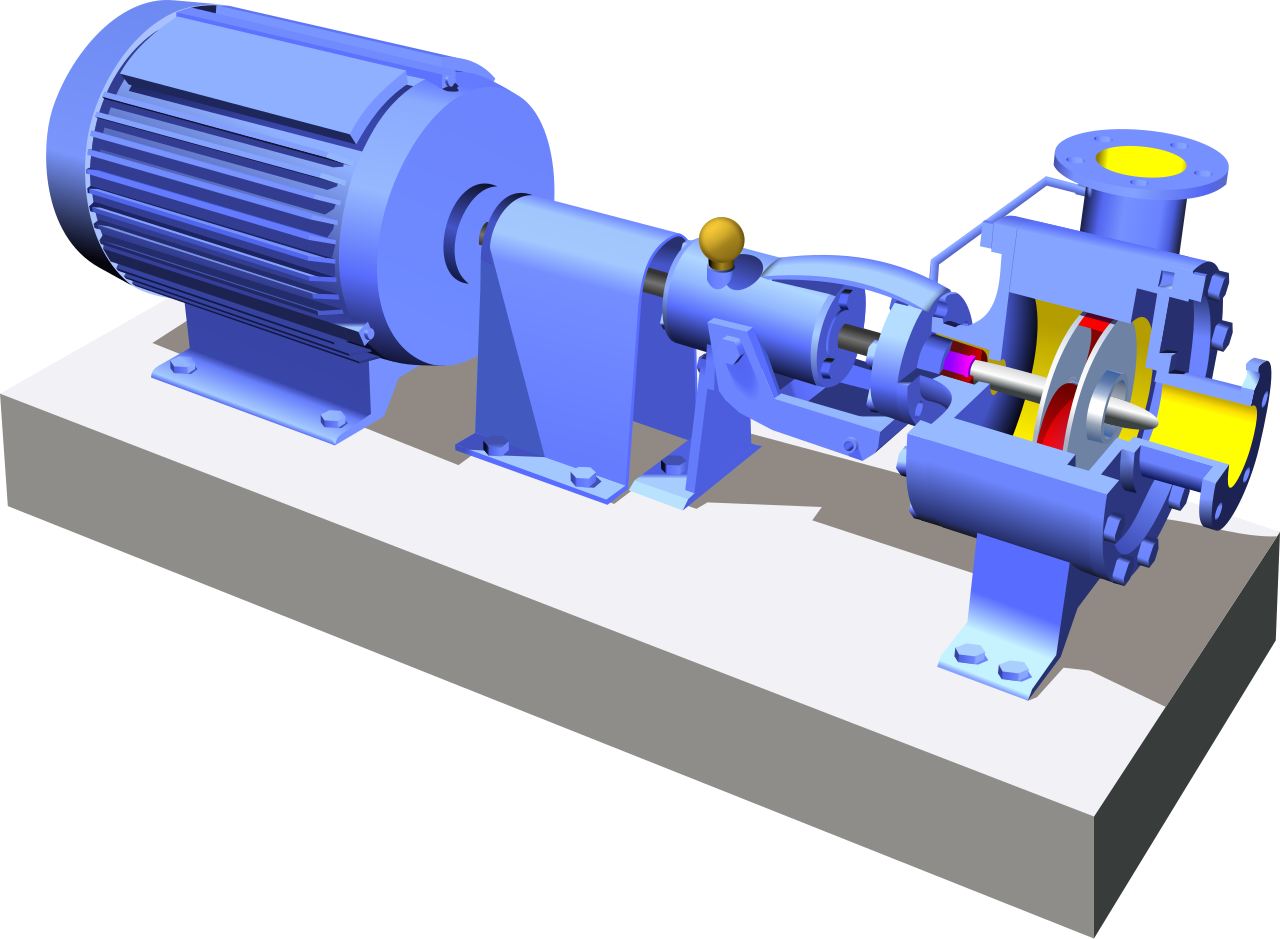
The electrical system controls the motor, but pump protection must also respond to hydraulic conditions at the inlet, impeller and outlet. Illustration: Magasjukur2, CC BY-SA 3.0, via Wikimedia Commons.
5. Match the control relay to the coil and controller
After choosing the power device, select the control relay from the contactor coil and the controller output. An electromagnetic coil can draw substantially more current during pull-in than after the armature closes. A PLC output or relay contact sized only from sealed coil current may fail during pull-in.
| Check | Question | Risk if missed |
|---|---|---|
| Coil supply | Exact voltage, AC/DC, frequency and tolerance? | No pickup, overheating, buzzing or wrong replacement |
| Voltage at A1-A2 | Value during pump start, longest cable and minimum supply? | Chatter, contact damage or unintended dropout |
| Coil burden | Pull-in VA/current and sealed VA/W? | Undersized PLC output, transformer or interface contact |
| Contact duty | AC-15, DC-13, minimum load and required life? | Early wear or intermittent low-level feedback |
| Suppression | Built-in diode, TVS, MOV or RC; correct polarity and release? | Driver damage, EMI or delayed interlock release |
| Socket/terminal | Wire size, torque, retention, labels and spare availability? | Heating, loose wiring and incorrect field replacement |
An interposing relay is useful when it protects a small float or PLC output, adapts voltage or source/sink logic, adds contacts, or creates a replaceable service point. It is not automatically required. Every added relay introduces terminals, delay, coil power, and another possible failure, so add it for a defined reason.
For QIANJI options, compare general-purpose relays for control/interface duty and compatible relay sockets for panel mounting and service. Final approval still depends on the exact model's coil, contact-load, insulation, life, terminal, temperature, and certification data.
6. Treat sensors as real electrical loads
Float switches, pressure switches, electrodes, and transmitters work in wet, noisy environments and may use long cables. Confirm whether the field device provides a dry contact, powered semiconductor output, two-wire leakage current, analog signal, or proprietary interface. A float marked "10 A" may be rated for a resistive load, not a contactor coil or pump motor.

A float switch contains a small switching mechanism; its motor or inductive-load rating must be verified rather than inferred from a resistive value. Photo: Martin Meise, CC BY 3.0, via Wikimedia Commons.
Prevent short cycling
Wave motion, tight pressure differential, a failed pressure vessel, or a leaking check valve can make a pump start and stop rapidly. Correct the hydraulic cause and create adequate start/stop separation or controller hysteresis. Minimum run and minimum off timers can help, but they must never delay a genuine overload, dry-run, emergency, or other protection trip.
Define sensor-failure behavior
Document the response to an open, shorted, grounded, stuck, or disconnected sensor. The safer state depends on the process: a sump may need backup pumping to prevent flooding, while a well may need immediate shutdown to prevent dry running. Critical systems may justify independent high-high or low-low sensing, separate alarm power, and proof that commanded flow actually appears.
7. Build protection in separate layers
A contactor is a switch, not a complete protection system. Start from the failure modes: short circuit, sustained overload, phase loss, reversal, dry source, blocked discharge, seal leak, winding overtemperature, failed start, and rapid cycling. Each fault needs a suitable detection and interruption path.
| Fault | Typical response layer | Key boundary |
|---|---|---|
| Short circuit | Fuse, circuit breaker, or rated motor-protection device | Must suit available fault current and tested coordination |
| Sustained overload or stall | Thermal/electronic overload or motor-protection relay | Does not automatically replace short-circuit interruption |
| Phase loss, reversal or unbalance | Phase monitor, advanced motor protection, or drive | Verify threshold, delay and actual covered functions |
| Dry running | Level, pressure, flow, current/power or pump controller | Hydraulic protection; it does not increase contact capacity |
| Seal leak or motor temperature | Pump sensor and dedicated monitor/controller | Match the exact sensor type, isolation and proof-test method |
| No flow after command | Flow/pressure proof with time comparison | A contactor auxiliary alone does not prove water movement |
The Schneider Electric explanation of Type 2 coordination shows why the contactor, overload relay, and short-circuit protective device must be evaluated as a specific combination. Do not mix catalog parts and assume the published coordination result still applies.
Grundfos guidance notes that dry running can damage pump bearings and shaft seals and describes pressure/level switches and analog pressure/level transmitters as water-shortage detection methods. Choose the method from the hydraulic system and verify it across the allowed flow, speed, suction, and restart conditions.
8. Adapt the architecture to the starting method
| Pump system | Normal control role | Critical check |
|---|---|---|
| Small single-phase line-started pump | Float/pressure command to motor-rated relay or contactor | Explicit single-phase motor rating and correct pole arrangement |
| Three-phase DOL pump | Control relay to three-pole AC-3 contactor/starter | Nameplate FLA, starting time, overload and short-circuit coordination |
| Star-delta or reversing system | Timed/interlocked multi-contactor sequence | Manufacturer selection, mechanical/electrical interlocks and transition duty |
| Soft-starter pump | Relay commands starter input and reports state | Built-in versus external overload protection and bypass architecture |
| VFD pump | Relay commands drive run/enable or permissive input | Do not cycle an output contactor while the drive produces voltage |
| DC or solar pump | Controller enable/alarm or explicitly DC-rated switching | DC arc, polarity, voltage, controller functions and isolation |
Important VFD boundary
For a variable-frequency drive, routine start and stop should normally be applied to the drive control input. Schneider Electric states that using a contactor between the VFD output and motor to cycle the motor is a misapplication and can damage the drive or motor. If an output disconnect or contactor is required for isolation, bypass, or multi-motor service, follow the exact drive manual, feedback, timing, and interlock sequence. See the manufacturer's output-contactor guidance and output-disconnect guidance.
9. Design duplex and multi-pump logic for failure
An alternating relay can rotate the lead pump on successive cycles, helping balance starts or runtime. It does not replace independent switching and protection for each pump. A complete duplex or triplex design must also handle lag demand, a failed lead pump, maintenance isolation, high-high level, conflicting commands, communication loss, and simultaneous calls after an outage.
- Lead alternation: define whether alternation occurs after a completed cycle, by runtime, or by another event.
- Lag staging: set a distinct level or pressure threshold and verify that starts do not occur unintentionally together.
- Failed-pump override: compare command with current, pressure, or flow proof and start the available standby pump when required.
- Power restoration: document automatic, staged, or manual restart and prevent uncontrolled simultaneous inrush.
- Independent alarm: high-high level or critical low-water protection may need separate sensing and power based on the consequence study.
10. Check environment, electrical life, and maintenance
Pump controls may face condensation, spray, sewage gas, fertilizer, salt air, dust, insects, vibration, direct sun, or high altitude. A relay inside a rated enclosure is not automatically protected if cable entries, drains, heaters, ventilation, or field modifications compromise the complete assembly. Apply the component manufacturer's temperature and altitude derating and verify the installed enclosure and glands.
Estimate electrical operations from real pump duty. For example, 24 starts per day equals about 8,760 start cycles per year before test runs, abnormal cycling, or future demand. Compare expected operations with the manufacturer's electrical-life data at the actual load category, voltage, current, and operating rate. Mechanical-life values measured without switching the application load are not a substitute.
A plug-in relay and socket can simplify service, but verify socket current, insulation, terminals, retention clip, orientation, vibration resistance, and replacement keying. Track starts, runtime, overload trips, phase alarms, failed starts, and hydraulic proof where the service consequence justifies condition-based maintenance.
11. Validate the complete panel before approval
A good relay data sheet does not prove that the assembled panel will work. Test production-intent relays, sockets, contactors, overloads, control power, sensors, wire lengths, suppression, terminals, and enclosure. Record the exact part numbers, coil codes, settings, and approved substitutions.
| Test | Condition | Evidence to keep |
|---|---|---|
| Architecture review | Compare one-line, control schematic, BOM and wiring | Every switched load and protection function identified |
| Coil margin | Minimum supply, hot panel, longest field cable, simultaneous start | Measured voltage within operate and hold limits without chatter |
| Start/stop duty | Representative head, flow, voltage and allowed start rate | No nuisance trip, abnormal heating or delayed release |
| Protection logic | Safely simulate overload input, sensor fault, phase or dry-run signal | Correct trip, alarm, reset policy and backup sequence |
| Power restoration | Restore power with no call and with multiple pump calls | Intended restart, staging, priority and no uncontrolled start |
| Thermal/environment | Maximum intended current at worst enclosure ambient | Temperatures, seals, glands and terminals within ratings |
12. Send suppliers a complete RFQ
A supplier can confirm a relay only when the actual duty is visible. Ask for the exact part number and the data-sheet line or selection table that supports the proposed load. A claim such as "30 A relay" is not enough for a pump application.
| RFQ group | Required information | Supplier evidence |
|---|---|---|
| Motor and supply | Model, kW/hp, voltage, phase, frequency, FLA, start current/time | Motor-duty table at the exact voltage and category |
| Sequence and life | DOL/VFD/soft start, starts/hour, annual cycles, lead-lag logic | Electrical-life curve and operating-rate limit |
| Control interface | Control supply, coil pull-in/sealed burden, PLC/float output, cable | Coil range, AC-15/DC-13 data, suppression and release time |
| Protection | Overload, short circuit, phase, dry run, seal, temperature, alarms | Coordination table, setting ranges and function list |
| Site and compliance | Ambient, altitude, moisture, corrosion, fault current, destination | Derating, enclosure limits, approvals and test documents |
QIANJI can review control-interface needs using its control relay range, power relay range, solid-state relay range, and relay sockets. A power or solid-state relay should switch pump current only when the exact model is explicitly approved for that motor duty and the complete thermal, surge, isolation, protection, and failure-mode design is documented.
Need a relay-interface review for a pump control panel?
Send the motor nameplate, supply, starting method, control voltage, coil burden, sensor/output type, starts per hour, protection list, environment, approvals, expected quantity, and schematic. QIANJI can identify suitable relay and socket candidates for evaluation without treating a resistive current as a motor rating.
Send Your Pump-Control Requirements13. Avoid these common selection shortcuts
Do not approve a substitute because its coil voltage and pin pattern match the old relay. The replacement must also match the contact form, real load category, minimum switching load, electrical life, insulation, terminal and socket ratings, suppression, release behavior, ambient limits, and approvals. A visually interchangeable relay can behave very differently during coil pull-in, motor start, low-level feedback, or a hot-panel restart.
Do not solve early contact failure simply by choosing a larger resistive-current number. First check whether the original device carried motor current without a motor rating, whether the contactor coil voltage collapsed during pump start, and whether hydraulic short cycling raised the operation count. Also inspect loose terminals, incorrect overload settings, phase problems, long acceleration, contamination, and an unsuitable enclosure.
Do not treat a relay indicator, audible click, or contactor auxiliary contact as proof that the pump is delivering water. A complete diagnostic path compares the command with electrical feedback and, where the process requires it, pressure, flow, or level response. This distinction is especially important in unmanned wells, lift stations, booster systems, and duty/standby installations.
Finally, do not allow automatic restart to remain an undocumented default. Decide what happens after power loss, sensor recovery, overload reset, dry-run recovery, communication loss, and repeated failed starts. Drainage service may need automatic staged restart, while maintenance or process hazards may require manual reset. The correct response comes from the site risk assessment.
Frequently asked questions
Can a normal relay switch a water pump directly?
Only when its data sheet gives an explicit motor or horsepower/kilowatt rating for the actual voltage, phase, starting method, and duty, and the complete protection requirements are met. A general resistive current rating alone is insufficient. Most larger AC pumps should use a contactor or starter.
What size relay is needed for a 1 hp pump?
There is no safe answer from horsepower alone. Obtain voltage, phase, frequency, nameplate full-load current, starting current/time, starting method, and starts per hour. Then use the device manufacturer's motor table at that exact voltage and phase.
Why can a 16 A relay fail on a 10 A pump?
The 16 A value may describe a resistive test load. A pump motor has high making current and inductive interruption, which can produce greater contact heating and arcing. Look for a specific motor-duty, AC-3, or horsepower rating.
What is the difference between a pump relay and a pump contactor?
A control relay normally handles logic and switches a coil or input. A contactor is designed to switch motor power repeatedly. "Pump relay" is an ambiguous market term, so identify the actual function and rating before purchase.
Does a contactor protect the pump from overload?
No. A basic contactor switches power. Use a coordinated overload relay, motor-protection device, or approved electronic protection arrangement, together with the required short-circuit protective device.
Can a float switch drive a contactor coil directly?
Yes only when the float contact is rated for that exact coil voltage, inductive inrush, operating frequency, cable, and environment. Otherwise use a suitable interposing relay or controller and verify the new coil load as well.
Which relay protects a pump from dry running?
Possible methods include low-level floats, electrode relays, suction-pressure switches, level or pressure transmitters, flow detection, power/current monitoring, and pump-integrated controllers. Select and validate the method for the hydraulic system; dry-run protection does not change the motor-switching contact rating.
Is a phase-monitoring relay needed for a three-phase pump?
It may be valuable where phase loss, reversal, undervoltage, overvoltage, or unbalance can damage the motor or reverse rotation. A drive or advanced motor-protection device may already cover some functions. Verify the exact thresholds, delay, and response.
How does an alternating relay work in a duplex pump system?
It changes the lead pump after a defined cycle or runtime so duty is shared. A lag threshold starts the second pump when demand exceeds one-pump capacity. Each pump still needs independent switching, protection, feedback, and failed-pump handling.
Should a relay switch the output of a VFD-controlled pump?
Routine start/stop should normally use the VFD control input. Do not open or close a downstream contactor while the drive is outputting voltage unless the drive manufacturer approves the exact sequence, auxiliary feedback, timing, and interlocks.
Final selection checklist
A dependable pump-control design separates sensing, control interfacing, motor switching, electrical protection, and hydraulic protection. The control relay is selected from its coil and contact load; the contactor or motor-rated device is selected from the motor duty; the overload and short-circuit devices are coordinated as a feeder; and monitoring functions are selected from real pump failure modes.
Before ordering, confirm the motor nameplate, starting behavior, operating rate, control voltage at the coil, pull-in and sealed burden, sensor interface, suppression, environment, fault level, restart policy, approvals, and expected electrical life. Then require the supplier to show the exact published rating evidence and validate the assembled panel under representative worst-case conditions.
Technical references
IEC 60947-4-1:2023; IEC 60947-5-1:2024; ABB Technical Application Papers No. 7; Schneider Electric VFD output-contactor and disconnect guidance; Schneider Electric Type 2 coordination guidance; Grundfos dry-running protection guidance. Always use the current edition and the exact product documentation required by the destination market.