


Testing solid state relays makes sure they work well and last. These relays are popular because they are tough, quiet, and switch often without breaking. They are used in factory machines, household devices, and car systems. Learning to test a relay is important to keep them working. Whether fixing problems or doing regular checks, testing solid state relays helps find issues early and avoid big failures.
Key Takeaways
-
Always wear safety gear like gloves and goggles to stay safe.
-
-
Use a multimeter to check resistance and if circuits connect well.
-
-
Test the relay with a load, like a light bulb, to see if it works properly.
-
-
Look for cracks, burns, or color changes on the relay before testing.
-
-
Regularly test and maintain relays to find problems early and make them last longer.
Tools and Equipment for Testing Solid State Relays

Multimeter for resistance and continuity testing
A multimeter is a key tool for testing relays. It measures resistance and checks if circuits connect. Set the multimeter to the 'R×10 k' range. Attach the black lead to the positive terminal and the red lead to the negative terminal. If the input voltage is 3 volts or more, resistance should drop to almost zero. This shows the relay's output contact has closed. If the needle doesn't move, the relay might be broken. This test helps you see if the relay works properly.
Power supply or control voltage source for input activation
You need a power supply to turn on the relay's input. Solid state relays use DC voltage between 3 and 32 volts. Pick a power source that matches the relay's needs. Send voltage to the input terminals and watch the relay's reaction. If it works, the relay will switch its output circuit. This step checks if the relay responds to signals correctly.
Test load, such as a light bulb or resistor, to simulate real-world conditions
Using a load tests how the relay works in real life. A light bulb or resistor is good for this test. Connect the load to the relay's output terminals. When you send voltage to the input, the load should turn on, like a bulb lighting up. This shows the relay can handle a load and switch properly. It's a simple way to check how the relay performs during normal use.
Safety gear, like insulated gloves and goggles, for protection
Always put safety first when testing solid state relays. Electrical testing can be dangerous with risks like shocks or burns. Wearing proper safety gear helps protect you from these dangers. Insulated gloves keep your hands safe from electricity. Safety goggles protect your eyes from sparks or flying debris.
Here are some important safety rules to know:
|
Rule/Standard |
What It Means |
|---|---|
|
Requires safety checks for electrical hazards since 2015. |
|
|
NFPA 70E |
Lists safety gear needed for different electrical tools. |
|
ASTM |
Sets rules for rubber gloves to resist electrical dangers. |
These rules show why certified safety gear is so important. Check your gloves for damage before using them. Make sure your goggles fit well and stay in place. Even low-voltage relays can cause accidents. Using safety gear lets you test without worrying about getting hurt.
Optional oscilloscope for detailed testing
An oscilloscope is helpful for advanced relay testing. It shows voltage and current as waveforms on a screen. This tool is great for spotting problems like delays or uneven switching.
To use it, connect the probes to the relay's input and output. Watch the waveform when you add control voltage. A steady signal means the relay works fine. If the signal has spikes or dips, the relay might have issues inside.
You don't need an oscilloscope for basic tests, but it's useful for deeper checks. It's a handy tool if you often work with solid state relays.
Preliminary Visual Inspection of the Solid State Relay
Start by looking closely at the solid state relay. This simple check can help spot problems that might affect how it works.
Look for cracks, burns, or discoloration on the relay
Check the relay's outer case carefully. Search for cracks, burn marks, or faded spots. These signs often mean the relay has overheated or been damaged. Focus on the edges and surface where damage is easier to see.
Tip: If the relay looks damaged, it may not work right. It's safer to replace it than try fixing it.
Here's a table to guide your inspection:
|
Step |
What to Do |
|---|---|
|
Visual Inspection |
Look for any clear signs of damage before testing the relay. |
|
Check for Damage |
Examine the relay case for cracks, burns, or other visible problems. |
|
Inspect Terminals |
Make sure terminals are clean and free of dirt or rust. |
Confirm the relay's label and specifications
Read the relay's label to check its details. Make sure the input voltage and output current ratings match your needs. Using the wrong relay can cause overheating or failure. If the label is missing or hard to read, don't use the relay until you confirm its specs from the manufacturer.
Examine the terminals for rust, loose parts, or dirt
Look at the relay's terminals for rust or dirt buildup. Dirty or rusty terminals can stop electricity from flowing properly. Check for loose screws or wires that might cause problems. Tighten anything loose and clean off dirt or rust.
Note: Maintenance logs often stress checking for rust and loose parts. Make this a regular habit.
Here's a checklist to follow:
-
-
Write down the condition of all connections.
-
-
Tighten screws to make sure they're secure.
-
-
Clean terminals to remove rust or dirt.
-
These steps help find problems early and get the relay ready for testing.
Step-by-Step Guide to Testing the Input Circuit
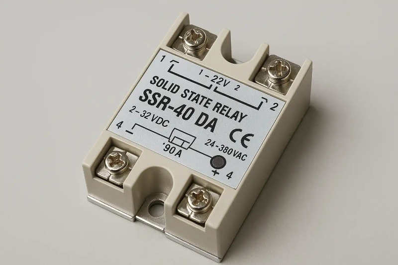
Testing the input side of a solid state relay checks if it works properly. Follow these simple steps to test its function.
Set the multimeter to measure resistance and connect it to the input terminals
Prepare your multimeter to measure resistance. Switch it to the Ohm (Ω) setting. If your multimeter has a 4-wire option, use it for better accuracy. This setup reduces errors caused by the test leads.
Here's how to set up your multimeter:
|
Step |
What to Do |
|---|---|
|
1 |
Connect the test leads to the multimeter's input terminals. |
|
2 |
Attach another set of leads to the calibrator's standby terminals. |
|
3 |
Inform the calibrator about the 4-wire connection. |
|
4 |
Turn the multimeter to the Ohm setting. |
|
5 |
Set the calibrator to source 10 Ohms. |
|
6 |
Press Operate to start the test. |
Once ready, connect the multimeter leads to the relay's input terminals. Make sure the connections are tight and match the relay's polarity.
Tip: Double-check your multimeter settings for accurate results.
Verify the input resistance to ensure the circuit is not shorted
Look at the resistance reading on the multimeter. A working relay should show high resistance when no voltage is applied. If the reading is very low or zero, the input might be shorted.
For more details, use the diode test mode on the multimeter. Switch to this mode and connect the leads to the relay's input terminals. A reading of about 0.7V (silicon) or 0.3V (germanium) means the relay is fine. If the reading shows "0" or "OL," the relay may be broken.
Note: Replace the relay if the input circuit is shorted.
Apply control voltage to the input terminals and observe the relay's response
Send the correct control voltage to the relay's input terminals. Most solid state relays work with DC voltage between 3 and 32 volts. Use a power supply that matches the relay's needs. For DC relays, connect a 9V DC source. For AC relays, use an AC voltage source.
Follow these steps to test the relay's response:
-
Connect a 9V DC power supply to the relay's input terminals.
-
-
Add a switch to control the input voltage.
-
-
On the output side, connect a light bulb as the load.
-
-
Turn the switch ON and OFF while watching the bulb.
-
If the bulb lights up when the switch is ON and turns off when the switch is OFF, the relay is working. This test shows the relay can handle signals and loads.
Callout: Make sure the control voltage matches the relay's input needs. Wrong voltage can damage the relay.
For advanced testing, use an oscilloscope to check the relay's response. It shows voltage waveforms and helps find switching problems.
Pro Tip: Fast-switching relays work well with hysteresis control methods.
By following these steps, you can test the input side of a solid state relay and confirm it works correctly.
Step-by-Step Guide to Testing the Output Circuit
Testing the output circuit of a solid state relay checks if it works well. Follow these steps to make sure it switches and handles loads properly.
Use a multimeter to check if the output terminals are open or closed
First, find out if the relay's output terminals are open or closed. This helps you know the relay's state before turning it on. A multimeter is needed for this test. Set it to "Continuity" mode, shown by a diode symbol.
Steps to follow:
-
Turn off the system to stay safe during testing.
-
-
Place the multimeter probes on the relay's output terminals.
-
-
Listen for a beep or check the resistance. Low resistance (a few ohms or less) means the circuit is closed. High resistance means it's open.
Tip: Continuity testing is fast and simple. Always turn off power to avoid accidents.
Turn on the relay by applying control voltage to the input
After checking the initial state, turn on the relay by adding control voltage to its input terminals. This step activates the relay so you can see how it switches. Use a power source that matches the relay's voltage needs, usually 3 to 32 volts for DC relays.
Steps to energize the relay:
-
Connect the power supply to the relay's input terminals.
-
-
Slowly increase the voltage to the correct level.
-
-
Watch the relay's reaction. You might hear a soft click or see a light turn on if it's working.
-
Note: Use the right voltage to avoid damaging the relay. For DC relays, a 9V DC source works well. AC relays need an AC voltage source.
Check the output voltage or current to confirm switching
Once the relay is on, measure the output voltage or current to see if it switches correctly. This step shows if the relay can handle loads. Use a multimeter to measure voltage or current, depending on the relay type.
Steps to test the output:
-
Attach a test load, like a light bulb, to the relay's output terminals.
-
-
Use the multimeter to measure voltage across the output terminals.
-
-
Turn on the relay by applying control voltage.
-
-
Look at the multimeter reading. A big change in voltage or current means the relay is switching properly.
-
For more detailed tests, use special tools:
|
What It Does |
|
|---|---|
|
Primary Injection Test Set |
Lowers voltage to test high current circuits like relays and breakers. |
|
Relay Test Set |
Mimics power system conditions to test solid-state and advanced protection devices. |
|
Power Factor Test Set |
Measures voltage and current to check insulation and power factor in high-voltage equipment. |
Pro Tip: Try accelerated life testing (ALT) for deeper checks. ALT uses high temperatures and fast switching to mimic long-term use. It helps find weak points and ensures the relay lasts.
By following these steps, you can test the output circuit of a solid state relay. This ensures it works well in real-life situations.
Test the relay with a load, like a light bulb, to see how it works in real life
Testing a solid state relay with a load shows how it works in real situations. This test checks if the relay can switch and run devices properly. Follow these steps to test the relay using a light bulb.
Step 1: Get Your Tools Ready
Gather everything you need for the test. You'll need:
-
The solid state relay you want to test.
-
-
A light bulb or resistor to act as the load.
-
-
A power supply that fits the relay's input voltage.
-
-
Insulated wires to make safe connections.
-
Tip: Pick a light bulb with a wattage lower than the relay's limit. This avoids overloading during the test.
Step 2: Attach the Load to the Relay
Connect the light bulb to the relay's output terminals. Make sure the connections are tight and match the relay's polarity. If the relay has screws, tighten them well to avoid loose wires.
Here's a simple connection guide:
|
Component |
Where to Connect |
|---|---|
|
Light bulb |
To the relay's output terminals |
|
Power supply |
To the relay's input terminals |
Step 3: Turn on the Relay with Voltage
Power the relay by sending the right voltage to its input terminals. Most solid state relays use DC voltage between 3 and 32 volts. Use a power supply that matches the relay's needs.
Steps to follow:
-
Attach the power supply to the relay's input terminals.
-
-
Slowly raise the voltage to the correct level.
-
-
Watch how the relay reacts.
-
Callout: If the relay works, the light bulb will turn on when voltage is applied. This means the relay is switching correctly.
Step 4: Check Switching On and Off
Turn the relay on and off a few times to test it. Use a switch or adjust the control voltage manually. Watch the light bulb closely. It should light up when the relay is on and go off when it's off.
Note: If the bulb flickers or doesn't work, check the wiring and make sure the input voltage is correct. Bad connections or wrong voltage can cause problems.
Step 5: Test the Relay's Load Handling
Keep the relay on for a few minutes to see if it can handle the load. Look for overheating or strange behavior. A good relay will stay cool and keep the light bulb running smoothly.
Pro Tip: If the relay gets too hot, lower the load or check if the relay matches your setup.
By following these steps, you can test how the relay works in real-life conditions. This helps you know if the relay is reliable and ready for use.
Troubleshooting Common Issues When Testing Solid State Relays
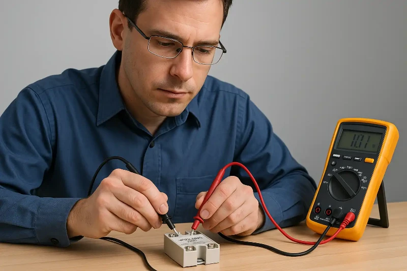
Problems can happen even with the right tools and steps. Knowing how to fix them helps keep relays working well.
Fixing no response from the input circuit
If the relay's input doesn't respond, check the control voltage first. Use a multimeter to see if the voltage matches the relay's needs. Wrong or missing voltage often causes this problem. Look at the input terminals for loose wires or rust. Clean them and tighten any loose parts.
Next, measure the relay's input resistance with a multimeter. High resistance means the circuit works fine. Low or zero resistance may mean the circuit is shorted. Replace the relay if this happens. For deeper checks, use an oscilloscope to see the input signal shape. This tool finds problems in fast-switching relays.
Tip: Always check the power supply before testing. A bad power source can give wrong results.
Fixing output circuit switching problems
If the relay's output doesn't switch, test the output terminals first. Set the multimeter to continuity mode to see if the circuit is open or closed. If it stays open after adding control voltage, the relay might be broken.
Check the load connected to the relay. Make sure it doesn't use more current than the relay allows. Too much current can stop the relay from switching. For AC relays, measure the voltage across the output terminals. A big voltage drop shows the relay is switching correctly.
Callout: Replace the relay if it can't handle the load or fails after testing.
Fixing intermittent or uneven performance
Relays that work sometimes may have loose wires or heat damage. Check all connections to make sure they're tight. Look for burns or faded spots on the relay's case. Too much heat can cause uneven performance.
If the relay is in a place with lots of shaking, make sure it's mounted tightly. Vibrations can loosen wires over time. For fast-switching relays, use an oscilloscope to check how it works. Strange waveforms may mean the relay is worn out or damaged.
Pro Tip: Test relays often and under real conditions to avoid these problems.
Fixing these common issues helps your solid state relay work safely and reliably.
Finding reasons for overheating or strange noises during use
If a solid state relay overheats or makes noise, something is wrong. Fixing these problems early can stop damage and keep it working well. Here are common reasons and how to fix them.
1. Check the Heat Sink
Solid state relays get hot when they work. Without a good heat sink, heat builds up and causes problems. Look at the heat sink to see if it's installed right. Make sure it's big enough to handle the relay's heat. If it's loose or too small, replace it with the correct size.
2. Improve Heat Dissipation
Bad heat dissipation can cause overheating. Dust or dirt on the relay blocks airflow and makes cooling harder. Clean the relay and nearby parts often. Put the relay in a spot with good airflow. If it still overheats, add a fan or get a better heat sink.
3. Check for Thermal Protection
Some relays have thermal protection that shuts them off when too hot. This stops permanent damage. If your relay shuts off a lot, it might be overheating. Look at the relay's manual to see if it has this feature. Fix the main problem, like too much load or bad airflow, to stop it from shutting down.
|
Overheating Cause |
What It Means |
|---|---|
|
Thermal Protection |
Stops overheating by shutting off before damage happens. |
|
Heat Sink Problems |
Shows issues with size or setup of the heat sink. |
|
Heat Dissipation Issues |
Checks how well the system cools to avoid overheating. |
4. Solve Strange Noises
Solid state relays should be quiet. Buzzing or clicking means something is wrong. It could be loose wires or a bad part. Check the input and output wires and tighten them. If the noise doesn't stop, use a multimeter to find internal problems.
Tip: Clean and check connections regularly to avoid overheating and noise.
Fixing these problems helps your solid state relay stay safe and work well.
Testing solid state relays needs careful steps to check they work well. First, look closely for cracks or damage on the relay. Next, test the input and output circuits to make sure they function properly. Always use the correct tools and wear safety gear to stay safe. Following these steps helps you test the relay correctly and keep it working longer.
Tip: Testing solid state relays often helps find problems early and avoids expensive repairs.
FAQ
What is the safest way to test a solid state relay?
Wear gloves and goggles to stay safe. Use tools like a multimeter and power supply with correct voltage. Always turn off power before touching wires. Follow safety rules like OSHA and NFPA 70E for electrical work.
Can you test a solid state relay without a load?
Yes, you can check the relay's input and output using a multimeter. But testing with a load, like a light bulb, shows how it works in real situations. This helps confirm the relay can handle devices correctly.
How do you know if a relay is overheating?
Touch the relay to see if it feels too hot. Look for burn marks or use a thermometer to check the temperature. If it shuts off often, it might have thermal protection. Clean it and improve airflow to stop overheating.
What should you do if the relay doesn't switch?
Use a multimeter to check if the control voltage is correct. Look for loose wires or rust on the connections. If it still doesn't work, test the output terminals for continuity. Replace the relay if it fails these checks.
Is an oscilloscope necessary for testing relays?
You don't need an oscilloscope for simple tests. It helps with advanced checks, like seeing voltage waveforms or finding delays. If you work with fast relays or need detailed results, an oscilloscope is useful.