

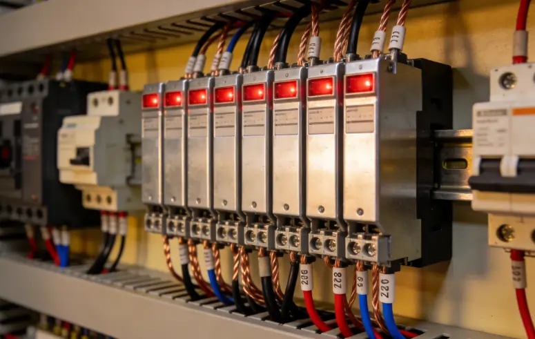
When you design a PLC control system, you face a critical decision. How do you connect the PLC's digital outputs to real-world devices? The challenge is clear: you need to safely bridge the gap between the low-power, delicate electronics of the PLC and the high-power, electrically noisy world of motors, solenoids, and lamps.
The solution is a fundamental component called the intermediate relay. Think of this device as the essential "bodyguard" for your PLC's output module. It's not just an add-on. It's a cornerstone of professional control panel design.
Using an intermediate relay is a fundamental best practice. It helps you create robust, safe, and easily maintainable automation systems. Its value comes from three core benefits that we'll explore in detail.
Signal isolation
Load amplification
PLC output protection
What Is an Intermediate Relay?

An intermediate relay is a crucial interface component within a PLC control system. Some people call it an interposing relay or control relay. It works as an electrically operated switch that translates a low-energy signal from the PLC into a high-energy action in the field.
The PLC's Heavy-Duty Assistant
Here's a simple analogy to clarify its function. Imagine the PLC output is your finger. It can press a small button with minimal force. The intermediate relay is the mechanism that this button activates.
This mechanism has the strength to engage the starter for a large industrial motor. Your finger can't start the motor directly. But it can easily and safely control the device that does.
The intermediate relay is an electromechanical or solid-state switch. It uses a small amount of power from the PLC output to control a completely separate and often much higher-power electrical circuit.
Key Relay Components
A standard plug-in intermediate relay consists of a few primary parts that work together. These are common in control panels.
Coil: This is the input side of the relay. When you energize it with the correct voltage from the PLC output, it creates a magnetic field.
Contacts: This is the output switch side. The magnetic field from the energized coil moves a mechanism that physically opens or closes these contacts. They include Common (C), Normally Open (NO), and Normally Closed (NC) terminals.
Base/Socket: This housing mounts directly onto a DIN rail in the control panel. It has screw terminals for wiring and allows the relay to be plugged in or removed without touching the wiring. This makes replacement simple.
Relay vs. Output vs. Contactor

New technicians often get confused when distinguishing between a PLC's internal output, an intermediate relay, and a larger power contactor. Each has a distinct role and capacity.
|
Feature |
PLC Transistor Output |
Intermediate Relay |
Power Contactor |
|
Typical Current Rating |
0.1A - 2A |
3A - 16A |
9A - 2000A+ |
|
Primary Function |
Low-energy logic signal |
Signal isolation, amplification |
High-power load switching |
|
Switching Voltage |
Typically 24V DC |
24V DC to 250V AC |
24V DC to 690V AC+ |
|
Cost of Failure |
High (module replacement) |
Low (relay replacement) |
Medium (contactor replacement) |
|
Use Case |
Driving a relay coil |
Driving a contactor coil, small motor, lamp |
Driving large motors, heaters |
The Three Non-Negotiable Pillars
We call the core functions of an intermediate relay the three pillars of professional PLC interfacing. Understanding these shows why they are essential components in any serious control system design.
Pillar 1: Signal Isolation
The most important function of an intermediate relay is providing galvanic isolation. This means there's no direct electrical path between the circuit controlling the relay coil (the PLC) and the circuit being switched by the relay contacts (the load).
This air gap or physical separation is a powerful tool for system integrity and electrical safety.
The load side of a system can be an electrically hostile environment. It includes motors, variable frequency drives, and solenoid valves. These devices can generate significant voltage spikes, electrical noise, and high-frequency transients back onto the power line.
Without an intermediate relay, this electrical noise would travel directly back into the PLC's sensitive output card. This could cause erratic behavior or permanent damage. The relay acts as a robust buffer that absorbs these disturbances.
Another critical issue in large systems is the potential for ground loops. When the PLC and a field device are powered from different sources or are physically far apart, their "ground" or 0V reference points may be at slightly different electrical potentials.
Connecting them directly can cause unwanted currents to flow. This leads to unreliable signaling. Because the relay's coil and contact circuits are isolated, it breaks these potential ground loops and ensures clean signal transmission.
The most common use case is interfacing different voltage levels. A PLC control system almost always operates on 24V DC for its logic. However, the devices it needs to control often run on 120V AC or 230V AC. These include motor starters, pumps, or large indicator lights.
An intermediate relay makes this translation simple and safe. The 24V DC PLC output energizes the relay's 24V DC coil. The relay's contacts are rated for the higher voltage. They then safely switch the 120V AC power to the load.
Pillar 2: Load Amplification
PLC output modules are designed for signaling, not for power delivery. Their internal switching components are typically transistors. These are small and have very limited current-handling capabilities.
A standard PLC transistor output might be rated for only 0.5A. In contrast, the coil of a small motor contactor can have an inrush current of 2A or more for a few milliseconds when it first energizes.
Connecting this contactor coil directly to the PLC output would create an overcurrent condition. This would instantly destroy the output transistor. It would render that output channel on the PLC module permanently useless.
The intermediate relay functions as a current amplifier. It takes a very small input signal from the PLC to energize its coil. This is often as little as 15mA (0.015A).
In response, its internal contacts can safely switch a much larger current. This is typically in the range of 5A to 10A. This bridges the significant power gap between the PLC's signal and the load's demand.
It's also crucial to understand the difference between load types. A resistive load has a predictable and steady current draw. Examples include a simple heater or incandescent bulb.
An inductive load is far more demanding. Examples include a motor, solenoid, or contactor coil. These loads have a magnetic coil that creates a high inrush current upon energization. They also present other challenges upon de-energization. The robust contacts of an intermediate relay are designed to handle the rigors of switching these inductive loads.
Pillar 3: Sacrificial Protection
From a practical and financial standpoint, the intermediate relay serves as cheap insurance for your expensive PLC hardware. This is one of the most compelling arguments for their use.
Consider the cost. A standard plug-in intermediate relay and its base might cost between $10 and $20. A replacement 16-point digital output module for a major PLC brand can easily cost $300 to $500, or even more.
If a fault condition occurs, the intermediate relay will be the component that fails. Examples include a short circuit in the field wiring or a load failure. It's a simple, quick, and inexpensive task to unplug the failed relay and plug in a new one. Without it, the failure would destroy a channel on the PLC module. This requires a much more expensive and time-consuming replacement.
The number one silent killer of PLC DC outputs is a phenomenon known as inductive kickback, or back EMF.
When you apply a DC voltage to an inductive coil, a magnetic field builds. Examples include the coil of a relay or solenoid. When you remove that voltage, the magnetic field collapses rapidly. This collapsing field induces a voltage spike in the reverse direction across the coil. It can reach hundreds or even thousands of volts for a microsecond.
This high-voltage spike travels back to the PLC output that was controlling the coil. It can puncture the delicate semiconductor material of the switching transistor inside the PLC module, destroying it.
An intermediate relay allows us to easily add a simple protection component. We place a flyback diode directly across the relay's coil terminals to safely dissipate this energy. This protects the PLC, which is the primary goal.
Finally, all mechanical devices have a finite lifespan. A relay is rated for a certain number of switching cycles. In a high-frequency application, a relay may wear out after a few years of service.
It's far easier and more cost-effective to replace a $15 plug-in relay than to replace an entire PLC module. The PLC module may have its output components soldered directly to the circuit board. The relay is designed to be a consumable, maintainable part.
A Guide to Relay Selection
Moving from theory to practice requires selecting the correct intermediate relay for your specific application. We approach this as a systematic, four-step decision-making process to avoid common and costly mistakes.
Step 1: Match Coil to PLC
The first step is to ensure the relay's input (the coil) is compatible with the PLC's output.
The coil voltage of the relay must match the output voltage of your PLC. In modern control systems, this is overwhelmingly 24V DC. However, you must verify this on your PLC module's datasheet. Using a 12V DC relay with a 24V DC output will burn out the coil. The reverse will fail to actuate it.
You must also check the current draw of the relay coil. This value is found on the relay's datasheet. It's typically very low (e.g., 10-50mA). Ensure that the PLC output's maximum current rating is higher than the coil's current draw.
Step 2: Match Contacts to Load
Next, you must ensure the relay's output (the contacts) can safely handle the device you intend to control.
The relay contacts will have a maximum voltage rating. Examples include 250V AC or 30V DC. The voltage of your load circuit must not exceed this rating.
Calculate the maximum steady-state current your load will draw. Then, find the relay's contact current rating. We recommend selecting a relay with a contact rating at least 50% higher than your load's requirement. This provides a safe operational buffer and extends the relay's life.
Pay close attention to the specifications. Contact ratings are often different for AC and DC circuits. A contact rated for 10A at 120V AC might only be rated for 2A at 24V DC. This is because a DC arc is more difficult to extinguish than an AC arc when the contacts open. This leads to more wear.
Step 3: Determine Contact Form
You need to select the right contact configuration for your circuit's logic.
NO (Normally Open): The circuit path through the relay is open when the coil is de-energized. The path closes when the coil is energized. This is the most common configuration for turning a device on.
NC (Normally Closed): The circuit path is closed when the coil is de-energized. The path opens when the coil is energized. This is useful for fail-safe logic or turning a device off.
SPDT (Single Pole Double Throw): This provides one common terminal (C) that switches between one NO and one NC contact. It's also known as a "changeover" contact. It's useful for toggling between two different circuits or states.
DPDT (Double Pole Double Throw): This provides two independent sets of SPDT contacts that are both controlled by the same single coil. This is like having two relays in one package. It's useful for switching both the live and neutral of an AC circuit, or for controlling two separate circuits simultaneously.
Step 4: Consider Physical Features
Finally, consider the physical form factor and usability features that simplify installation and troubleshooting.
The industry standard is to use relays that plug into DIN rail mountable sockets. This allows for neat, secure mounting inside a control panel. It makes replacement a tool-free, 10-second job.
We highly recommend selecting relays or bases that include an integrated LED indicator. This small light provides immediate visual confirmation of the coil's status. It shows you at a glance whether the PLC is commanding the relay to be on or off. It's invaluable during commissioning and troubleshooting.
Some relays feature a manual test button or a locking lever. This allows a technician to manually actuate the relay to test the load-side wiring without needing the PLC program to be running. This can be a significant time-saver during system checkout.
Wiring Demystified
Properly wiring an intermediate relay in PLC control system is a critical skill. It involves two separate circuits: the low-voltage control side from the PLC and the often higher-voltage load side. We'll provide a step-by-step guide to making these connections safely and correctly.
Safety First: LOTO
Before touching any wire, you must follow proper Lockout/Tagout (LOTO) procedures. All power sources to the control panel must be de-energized, verified to be off, and locked in the off position. This includes both control and load power. This is the first and most important step in any electrical work.
The Control Side: Coil Wiring
Wiring the relay coil to the PLC requires understanding whether your PLC output module is a sinking or sourcing type. This is a primary source of confusion and wiring errors. Many of us have spent frustrating hours troubleshooting a circuit only to realize the common was wired for the wrong output type.
Sourcing outputs (PNP type) provide, or "source," +24V DC to the load. Sinking outputs (NPN type) provide a path to 0V DC, or "sink," current from the load.
[Diagram 1: Wiring for a Sourcing (PNP) Output. A wire runs from the PLC's digital output terminal to the relay's A1 coil terminal. A separate wire runs from the relay's A2 coil terminal to the 0V DC power supply common rail.]
For a sourcing (PNP) output, you connect the PLC output terminal directly to the A1 (positive) terminal of the relay coil. You then connect the A2 (negative) terminal of the relay coil to the 0V DC common bus.
[Diagram 2: Wiring for a Sinking (NPN) Output. A wire runs from the +24V DC power supply rail to the relay's A1 coil terminal. A separate wire runs from the relay's A2 coil terminal to the PLC's digital output terminal.]
For a sinking (NPN) output, the wiring is reversed. You connect the +24V DC power source to the A1 terminal of the relay coil. You then connect the A2 terminal of the coil to the PLC output terminal.
The Load Side: Contact Wiring
The load side wiring is independent of the control side. Here, you're simply passing power through the relay's switch contacts to your device.
We'll use the example of switching a 120V AC lamp using a Normally Open (NO) contact.
[Diagram 3: Wiring a 120V AC Load. A wire runs from the 120V AC Live/Hot circuit breaker to the relay's Common (C) contact terminal. A second wire runs from the relay's Normally Open (NO) contact terminal to one terminal of the lamp. A final wire runs from the other terminal of the lamp to the 120V AC Neutral bus bar.]
In this setup, the 24V DC control circuit and the 120V AC load circuit are kept completely separate. They're connected only by the magnetic field inside the relay. This is the essence of isolation.
The Essential Diode
As discussed earlier, protecting the PLC's sensitive DC output from the relay coil's inductive kickback is critical. This is accomplished by adding a flyback diode.
This diode is wired in parallel with the relay's DC coil terminals (A1 and A2). It's crucial that it's installed in reverse bias.
[Diagram 4: Showing Flyback Diode Placement. A small diode, such as a 1N4001, is shown connected across the A1 and A2 terminals of the relay base. The cathode, or striped end, of the diode is connected to the A1 terminal (the more positive side). The anode, or non-striped end, is connected to the A2 terminal (the more negative side).]
The striped end of the diode (cathode) must always connect to the positive side of the coil circuit. The non-striped end (anode) connects to the negative side.
Be extremely careful. If the diode is installed backward, it will create a direct short circuit from the power supply to ground as soon as the PLC output turns on. This will likely blow a fuse or damage the power supply.
A Cornerstone of Design
In conclusion, using an intermediate relay in a PLC control system is not an unnecessary complication. It's the mark of a professional, forward-thinking designer who understands the realities of industrial environments.
While it may seem like an extra component and an extra step in the design and wiring process, the benefits are overwhelming. It's a small investment that pays massive dividends over the life of the machine.
By incorporating an intermediate relay, you're building a holistic system that prioritizes PLC control, signal isolation, intermediate relay, electrical safety. It's fundamentally safer due to electrical isolation. It's more reliable due to noise immunity. And it's far easier and cheaper to maintain. These best practices separate a fragile prototype from a robust automation solution that will stand the test of time.
What is Rated Breaking Capacity? Complete 2026 Electrical Safety Guide
Contactless vs Mechanical Switches: Which is Right for You in 2026?
Switch Contact Arcing: Why Your Contacts Weld Shut & How to Stop It
Touch Switch Selection Guide 2026: Choose the Perfect Switch