

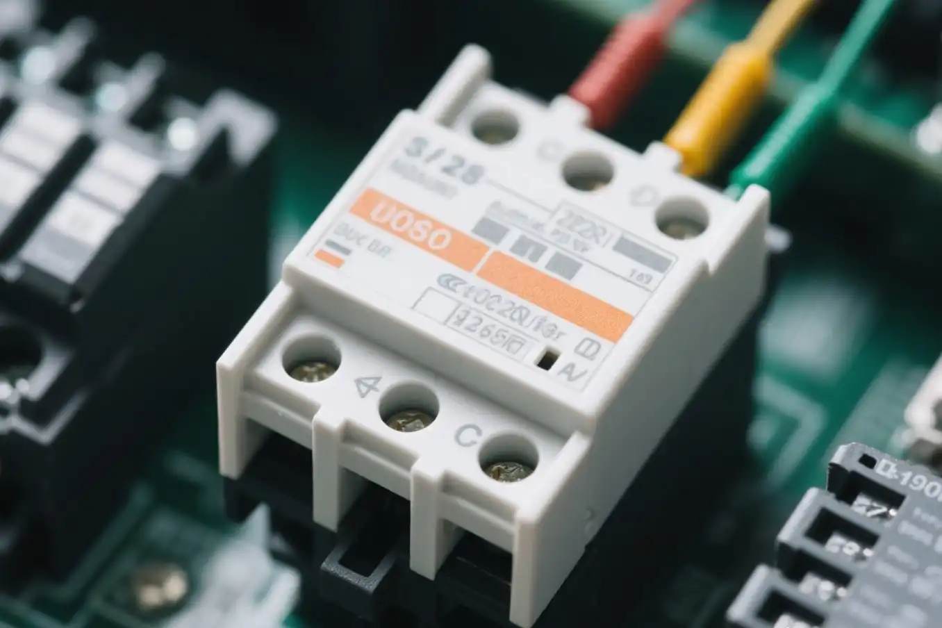
Use a direct PCB-mounted relay when compact board integration, repeatable high-volume assembly and a short electrical path matter more than field replacement. Use a plug-in relay with a socket when fast maintenance, accessible panel wiring, clear labeling or modular accessories justify the extra space, parts and connection interfaces.
Neither architecture is automatically more reliable or less expensive. The correct choice depends on the complete system: relay, socket or PCB, terminals, copper, wiring, accessories, enclosure, environment and service procedure. A relay contact rating alone does not approve the whole current path.
Important terminology: a "PCB relay" usually means a relay soldered directly to a printed circuit board. A "socket relay" usually means a plug-in relay inserted into a compatible socket. However, some plug-in relays use a socket that is itself soldered to a PCB, while relay interface modules combine a socket, DIN-rail base, terminals and other functions. Define the physical architecture before comparing price or performance.
Safety boundary: Plug-in construction does not mean hot-swappable. Unless the equipment design, component documentation, risk assessment and written procedure explicitly permit energized replacement, isolate all hazardous energy before removing a relay. Mains, high-voltage DC, safety-related, medical, rail, vehicle and hazardous-location systems need an application-specific standards and risk review.
PCB Relay vs Socket Relay: Quick Comparison
|
Decision Factor |
Direct PCB Relay |
Plug-In Socket Relay |
|---|---|---|
|
Best starting fit |
Compact OEM products, stable designs and controlled electronics production. |
Control panels, high-mix machines and equipment with planned field maintenance. |
|
Replacement |
Normally needs de-soldering, qualified board rework or replacement of the PCB assembly. |
Can be removed from the approved socket after safe isolation, without solder rework. |
|
Integration path |
Relay terminals, solder joints, PCB copper, connectors and harness. |
Relay pins, socket contacts, terminals, bridges, wire and field connectors. |
|
Space and BOM |
Usually smaller and has fewer separate parts. |
Usually larger and adds socket, retention and wiring hardware. |
|
Main control risk |
PCB layout, soldering, cleaning, trace heating and board-level repair. |
Exact compatibility, insertion, retention, terminal installation and spare-part control. |
|
Lifecycle economics |
Often favorable in volume, but a service event may cost more. |
Higher initial hardware cost can be offset by faster replacement and reduced downtime. |
Short decision rule: favor direct PCB mounting when the relay is a stable part of the board and the service policy accepts board replacement or qualified rework. Favor a socket or interface module when a technician needs controlled access to wiring and rapid relay replacement. If you need both board integration and replaceability, evaluate a PCB-mounted socket as a separate hybrid architecture.
1. First Define the Four Possible Architectures
The mounting method changes assembly, current paths, retention, maintenance and qualification. The four arrangements below can all be described loosely as "PCB relay" or "socket relay," but they are not interchangeable.
|
Architecture |
Typical Strength |
Primary Control |
|---|---|---|
|
Direct PCB-mounted relay |
Compact assembly, fewer pluggable contacts and good fit for automated production. |
Footprint, solder process, cleaning, copper temperature, isolation and repair method. |
|
Panel/DIN socket relay |
Accessible wiring and controlled replacement without PCB rework. |
Named relay/socket pairing, terminal system, retention, space, heat and safe service. |
|
PCB socket plus plug-in relay |
Replaceable relay with a board-level interconnect. |
Both PCB process risks and plug-in compatibility/retention risks. |
|
Relay interface module |
Standardized panel wiring and documented options such as indication, suppression or bridges. |
Exact module schematic, ratings, approvals, terminal behavior and accessory configuration. |

A direct PCB relay is selected and qualified as part of the board assembly. Image: Electronic component relay by FDominec, licensed under CC BY-SA 3.0 via Wikimedia Commons.
Compatibility is based on full part numbers, not appearance
A relay family may contain PCB-terminal and plug-in-terminal versions. Similar body size, pin count or coil voltage does not prove that a relay fits or is approved for a socket. OMRON's relay and socket compatibility FAQ, for example, states that a specified G2R plug-in-terminal type can use the named socket while PCB-terminal variants cannot. Its G2R socket table also identifies exact one-pole and two-pole pairings, terminal types and locking details.
That is a model-specific example, not a cross-brand rule. For every design, approve a named stack: relay model and coil option + socket model + terminal type + retainer + accessories + mounting + wiring or PCB interface.
2. When a Direct PCB Relay Is the Better Choice
Direct mounting is usually the stronger starting point when the relay is a stable part of an OEM board, space is limited and factory electronics assembly is already controlled. It removes the relay-to-socket spring-contact interface and can reduce component count, panel depth and manual wiring.
Typical fits include appliances, embedded controllers, power supplies, instruments, compact machine modules and other products where a failed control board is replaced as a unit. Review QIANJI's current PCB relay range by exact series, footprint, coil and contact requirement rather than selecting from body size alone.
Direct mounting transfers responsibility to the PCB and process
Removing a socket does not remove integration risk. The solder joint, plated hole or SMT land, trace, via, connector and harness become the current path. Board spacing, contamination, coating and enclosure conditions contribute to isolation performance. Heat from the coil, contacts and copper can raise the temperature of nearby components.
TE Connectivity's official PCB relay mounting and cleaning guidance warns that handling and mounting can alter relay operation. It also treats conductor width, board layout, soldering and cleaning as reliability controls. Use the exact relay data sheet for hole or land dimensions and process limits; do not transfer one manufacturer's solder or solvent recommendation to another relay.
Direct PCB design checklist
- Freeze the complete relay code, footprint and orientation in the controlled BOM.
- Verify trace width, copper weight, vias, connectors and solder-joint temperature at the actual load waveform and worst ambient.
- Check creepage, clearance, coating and contamination for the end-product voltage and environment.
- Qualify the real insertion, soldering, cooling, cleaning and coating processes with production-representative boards.
- Inspect for board flex, cracked joints, insufficient wetting, flux residue and wrong orientation.
- Define whether service means qualified rework or replacement of the full board, then test the approved repair route.
Direct PCB mounting often minimizes factory BOM and assembly time at volume, but include spare-board inventory, warranty handling, conformal-coating rework and field labor in the lifecycle calculation.
3. When a Plug-In Socket Relay Is the Better Choice
A plug-in socket architecture is usually a better fit when downtime, technician access and field wiring dominate the decision. After safe isolation, the approved relay can be replaced without soldering or replacing a complete board. The socket can organize screw, push-in or other documented terminal types, while labels and retention hardware make a controlled service process easier.
Socket systems are common in control cabinets, process equipment, high-mix machines, building controls and installations where local maintenance teams hold approved spares. They can also simplify panel variants when each permitted relay and accessory combination is tightly controlled.

A DIN-rail architecture needs space for terminals, wiring bend radius, labels, extraction and thermal management. Image: DIN rail by Ulfbastel, released into the public domain via Wikimedia Commons.
The socket is an electrical component, not a generic holder
The relay pins mate with spring contacts inside the socket. From there, current may travel through internal conductors, screw or push-in terminals, bridges, wire, ferrules and other terminal blocks. Each element has its own current, voltage, temperature, dielectric, retention and environmental limits.
Socket features also vary by exact code. A module may add an LED, diode, freewheeling circuit, fuse, test function or bridge system. Those options can change polarity, coil release behavior, fault response or isolation. Phoenix Contact's PLC-RSC interface-module example combines a plug-in miniature relay, terminal base, DIN mounting and an input/suppression circuit. It demonstrates what an interface module can include; it does not describe every socket relay.
Socket design and maintenance checklist
- Use the manufacturer's current compatibility matrix for the exact relay and socket.
- Check contact arrangement, coil code, terminal geometry, socket rating and accessory compatibility.
- Provide the specified lock, clip or retainer when vibration, orientation or service force requires it.
- Control wire gauge, strip length, ferrule or crimp, terminal tool and torque where applicable.
- Allow space for wire bend radius, labeling, inspection, ventilation and safe relay extraction.
- Publish an approved-spares list that prevents the wrong coil voltage, polarity, contact form or terminal version from being installed.
- Require a post-replacement identity, seating, wiring and functional check.
4. The Hybrid Case: A Plug-In Relay on a PCB Socket
A PCB-mounted socket can be valuable when the product needs board integration but relay replacement should not require de-soldering. The socket terminals are soldered to the board and the relay plugs into the socket. This arrangement may suit serviceable industrial control boards or expensive assemblies where replacing the entire PCB would create unnecessary downtime.
It does not eliminate PCB risks. Current still travels through socket solder joints and copper. Isolation still depends partly on board layout and contamination. At the same time, the design adds relay-pin-to-socket contacts, insertion depth, retention and wrong-spare risks. Treat the hybrid as a third architecture, not as a free combination of the benefits of the other two.
OMRON's current G2R lineup provides a useful product-specific illustration: it separately lists DIN/surface-mounting sockets and back-mounting sockets with PCB terminals for named plug-in relay versions. The lesson is architectural; always use the compatibility and process instructions for the parts actually ordered.
For qualification, test the relay, socket and finished board together. Include socket soldering, board flex, trace temperature, insertion and extraction, incomplete seating, retention, vibration, cleaning or coating, terminal mapping and repeated replacement assumptions.
5. The Weakest Element Sets the Usable Current Path
A relay marked with a contact rating does not automatically give the same rating to its socket, PCB traces, bridge, terminal or wire. Ratings are tied to named parts and test conditions. The usable design limit is set by the complete path under the actual load waveform, duty cycle, ambient temperature, enclosure, conductor installation and switching life requirement.
|
Path Area |
Direct PCB Architecture |
Socket Architecture |
|---|---|---|
|
Relay connection |
Relay terminal, solder fillet and PCB land or plated hole. |
Relay pin, socket spring contact and socket conductor. |
|
Load conductor |
Copper traces, vias, connectors and harness. |
Terminal clamp, bridge, wire, ferrule and terminal block. |
|
Isolation |
Relay insulation plus board creepage, clearance, coating and enclosure. |
Relay insulation plus socket spacing, terminal separation, bridges, routing and enclosure. |
|
Mechanical control |
Solder joints, board support, connector restraint and vibration behavior. |
Socket latch, retainer, DIN/panel mount, wire strain relief and extraction force. |
|
Thermal control |
Coil, contacts, solder, traces and adjacent components. |
Coil, contacts, socket contacts, terminals, wires and adjacent modules. |
OMRON's G2R specifications show why exact-model review matters. Within the named family, listed socket carry-current values differ between one-pole and two-pole socket models, and the dielectric details also depend on the exact socket. Those figures apply only to the listed OMRON combinations; they are not general relay-socket ratings.
Measure the assembled path
At minimum, measure voltage drop and temperature at the relay, socket or solder joint, terminal, copper or wire path and connectors while switching the actual load. Test the highest relevant ambient, enclosure density and duty cycle. Include inrush, motor starting, lamp cold current, capacitor charging or inductive release behavior where applicable.
Do not use a single room-temperature continuity check as proof. A loose terminal, partial insertion, undersized trace or high-resistance interface may become visible only after thermal cycling, vibration or sustained current.
6. Reliability, Vibration and Environmental Exposure
Direct PCB mounting removes one separable contact interface, but reliability still depends on relay quality, solder joints, board support, layout, heat, contamination and manufacturing control. A socket adds mating contacts and terminals, but a correctly matched and retained socket system can perform reliably in a demanding control panel.
Compare failure mechanisms rather than counting parts:
- Direct PCB: cracked or overheated solder joints, undersized copper, flux or cleaning damage, board flex, coating incompatibility and difficult rework.
- Socket: incomplete insertion, missing retainer, wrong replacement, loosened termination, corrosion, wiring strain and unapproved bridges or accessories.
- Both: contact overload, coil overvoltage or undervoltage, incorrect suppression, high ambient temperature, vibration, contamination and uncontrolled supplier changes.
Test the mounted assembly in the actual orientation. A component-level vibration value does not automatically approve a tall plug-in relay on a socket, a flexible PCB or field wires pulling on terminals. Monitor contact continuity and coil function during or after the relevant vibration and shock profile.
IEC's record for IEC 61810-1:2015 explains that the standard provides baseline functional and safety requirements for electromechanical elementary relays, while applications can impose additional requirements. Component compliance is evidence, not a substitute for final-equipment assessment.
7. Serviceability Does Not Mean Energized Replacement
A socket can shorten replacement time, but the maintenance design must control the whole event. Removing an energized relay may expose live terminals, interrupt an inductive current, create an arc, defeat an interlock or cause unexpected machine motion. Treat safe isolation, lockout/tagout and verification of absence of hazardous energy as the normal starting point.
After replacement, the technician should confirm:
- The full relay part number matches the approved spare, including coil voltage, AC/DC type, polarity or diode, contact form and terminal style.
- The relay is correctly oriented and fully seated in the named socket.
- The clip, lock or retainer is installed as required.
- Terminals, bridges and wiring show no heat damage, looseness or contamination.
- The coil driver and contact load are still within the approved operating conditions.
- The controlled equipment passes the documented post-maintenance functional test.
If relays fail repeatedly, replacement is not root-cause analysis. Capture coil voltage, load inrush, switching waveform, temperature, terminal voltage drop, environment and part-lot history before assuming the relay is the only failed element.
8. Compare Total Lifecycle Cost, Not Unit Price
A direct PCB relay can reduce parts, assembly operations and enclosure volume. A socket system adds hardware and panel space. However, the lowest purchase price may not create the lowest ownership cost.
Build the comparison from the expected product life:
- Annual production volume and degree of automated assembly.
- Engineering cost for PCB, panel, approvals and variant control.
- Factory wiring, inspection and end-of-line test time.
- Expected relay replacement rate and equipment downtime cost.
- Board rework capability, replacement-board logistics and warranty policy.
- Spare relay, socket, accessory or board inventory over the support period.
- Technician travel, safe access, replacement time and verification time.
- Cost of wrong replacements or uncontrolled field substitutions.
For a compact appliance made in stable high volume, direct PCB mounting often remains the better economic choice. For a process machine where one hour of downtime costs far more than the socket, a controlled plug-in architecture can recover its initial cost quickly. Use the actual forecast rather than a generic rule.
9. A Six-Step Selection Workflow
Step 1: Map the physical and electrical architecture
Draw the relay, socket if used, PCB, terminals, bridges, connectors, wire, enclosure and service access. Mark the complete coil and contact-current paths.
Step 2: Define production and service strategy
State annual volume, assembly method, repair-versus-board-swap policy, technician access, downtime cost, approved spares and expected support life.
Step 3: Freeze the complete configuration
Record relay series and full code, coil option, contact form, terminal type, socket, retainer, bridge, indicator, diode, fuse or suppression accessory, mounting and documentation revision.
Step 4: Check every electrical and thermal limit
Review steady current, inrush, load type, switching voltage, expected electrical life, coil drive, socket carry current, conductor heating, insulation, surge and ambient derating.
Step 5: Validate assembly and environment
For direct PCB mounting, qualify layout, soldering, cleaning, coating and board support. For sockets, qualify terminal installation, insertion, retention, accessories, panel/DIN mounting and service access. For PCB sockets, perform both groups of checks.
Step 6: Control production and field changes
Require review of changes to the relay, socket, terminal, material, plating, accessory, process, factory site, PCB or layout. Tie validation evidence to the sampled part numbers, manufacturing source and drawing revisions.
10. Validation Checklist Before Release
|
Validation Area |
Direct PCB Focus |
Socket / Module Focus |
|---|---|---|
|
Identity |
Relay code, orientation, date/lot and PCB BOM/revision. |
Relay, socket, accessory, retainer, bridge, label and approved spare codes. |
|
Assembly |
Footprint, solder profile/joints, cleaning, coating and board support. |
Terminal/wire installation, insertion, lock, DIN/panel mount and accessory seating. |
|
Electrical and thermal |
Trace, via, solder, connector temperature and voltage drop at actual load. |
Pin, socket, terminal, bridge and wire temperature and voltage drop at actual load. |
|
Insulation and safety |
Relay plus PCB spacing, contamination, coating, enclosure and field wiring. |
Relay plus socket spacing, terminal separation, bridges, routing and enclosure. |
|
Environment |
Mounted-board heat, humidity, vibration, contamination and process condition. |
Mounted base, retention, terminal strain, corrosion, vibration, access and wiring radius. |
|
Service |
Board replacement or rework instruction and post-repair test. |
Safe removal/insertion, part verification, locking and post-replacement test. |
Use production-representative samples, real wires or PCB copper, actual accessories and the intended enclosure. Record instruments, ambient conditions, loads, cycles, acceptance limits and sample identities so later supplier or design changes can be assessed against the same evidence.
11. Troubleshooting Architecture-Related Problems
|
Observed Problem |
What to Check |
Corrective Direction |
|---|---|---|
|
Relay or terminal is unusually hot |
Voltage drop and temperature across the relay, socket, terminal, solder, trace and wire; insertion and termination condition. |
Correct the limiting path element, load duty or assembly process; replace heat-damaged parts and retest. |
|
Output becomes intermittent after vibration |
Relay seating, retainer, terminal tightness, wire strain, socket contacts, board flex and solder joints. |
Improve retention, support or termination; then repeat mounted-assembly vibration testing with contact monitoring. |
|
Replacement relay does not operate |
Full part code, coil voltage, AC/DC type, diode polarity, pinout, contact form and socket compatibility. |
Install the approved exact spare and improve labeling, keying, training and parts control. |
|
PCB relay fails after cleaning |
Relay construction, cleaning permission, solvent, exposure, thermal shock and trapped contamination. |
Use a compatible relay/process combination and requalify cleaning, venting or coating steps. |
|
Failures return after repeated relay swaps |
Load inrush, coil driver, suppression, surge, heat, power quality, loose terminals, contamination and wrong replacements. |
Correct the external root cause and revalidate the complete path instead of treating replacement as the investigation. |
12. What to Put in a Relay RFQ
An effective RFQ describes the integration architecture and actual duty, not only coil voltage and a headline contact current. This allows the supplier to check the compatible relay, socket and accessories against the complete application.
|
RFQ Area |
Information to Provide |
Evidence to Request |
|---|---|---|
|
Architecture |
Direct PCB, panel/DIN socket, PCB socket or interface module; space, orientation and service access. |
Compatible configuration, dimensions, terminal map and mounting drawing. |
|
Electrical duty |
Coil supply/driver; AC or DC load; steady current, inrush, load type, switching rate, duty and ambient. |
Ratings and life conditions for the exact relay, socket, terminals and accessories. |
|
Process and mechanics |
PCB solder/clean/coating process or wire/terminal method; vibration, shock, enclosure and mounting. |
Process guidance, retention method, compatible tools/wire and sample drawings. |
|
Compliance |
Target market, end-product standard, insulation, environment and marking requirements. |
Current certificates, reports and approval scope tied to the proposed part numbers. |
|
Supply control |
Forecast, approved manufacturing site, traceability, spare policy and change-notification needs. |
Sample/lot identity, inspection plan, change-control terms and commercial supply documentation. |
For a QIANJI recommendation, send the relay or socket architecture, coil supply, contact load and inrush, PCB or field-wiring method, ambient/environment, service strategy, target certifications and annual quantity through the QIANJI inquiry page. Ask for the proposed full part numbers and supporting documents before qualification.
Frequently Asked Questions
Is a PCB relay the same as a socket relay?
No. A direct PCB relay is normally soldered to a board. A socket relay normally has plug-in terminals and fits a compatible socket mounted on a panel, DIN rail or sometimes a PCB. Always identify the full mounting architecture.
Are socket relays easier to replace?
Usually yes, because an approved plug-in relay can be removed after safe isolation without de-soldering. Replacement still requires the correct full part number, orientation, seating, retainer, wiring check and post-maintenance functional test.
Can I put a PCB-terminal relay into a relay socket?
Only when the manufacturer explicitly lists that terminal version as compatible with the exact socket. Family name, body size, pin count or coil voltage is not enough. PCB-terminal and plug-in-terminal variants may use different geometry or arrangements.
Does the relay contact rating also apply to the socket?
No. The socket, terminals, bridges, wire, PCB traces and connectors have their own ratings and conditions. The complete path must be checked for current, voltage, temperature, insulation and environment.
Are PCB relays more reliable than socket relays?
Not automatically. Direct mounting removes a mating interface but depends on soldering and PCB design. Socket systems add contacts and terminals but can be robust when correctly matched, retained, wired and maintained. Compare exact parts and validated failure mechanisms.
Can a plug-in relay socket be mounted on a PCB?
Yes, when the socket is designed for PCB mounting and the manufacturer approves the relay/socket pairing. This hybrid still needs PCB layout and solder qualification plus socket-contact, retention and replacement controls.
When is an interface module better than a bare socket?
It can be better when its documented terminals, indication, suppression, fuse, bridge or test features simplify the panel. Review the exact module schematic and part code because not every module includes the same functions.
What should be requalified when changing from PCB mounting to a socket?
Requalify part identity, terminal mapping, coil/driver behavior, contact load, voltage drop, temperature, insulation, wiring, insertion, retention, vibration, service procedure and every added accessory. The architecture change creates a new assembled current and mechanical path.
Final Recommendation
Choose a direct PCB relay when the product is compact, production volume is stable, board assembly is well controlled and the service model accepts board replacement or qualified rework. Choose a plug-in socket relay or interface module when accessible wiring, rapid controlled replacement, diagnostics and modular panel construction materially reduce lifecycle cost or downtime.
Then qualify the complete assembly. Freeze the relay, coil, socket, terminals, retainer, accessories, wiring or PCB and actual load as one approved configuration. The right architecture is the one that passes the electrical, thermal, insulation, environmental, production and service requirements of the finished equipment-not the one with the most attractive catalog headline.
Technical References
- IEC 61810-1:2015 - Electromechanical elementary relays: general and safety requirements
- TE Connectivity - Mounting, Termination, and Cleaning of PCB Relays
- OMRON - Compatible sockets for G2R relays
- OMRON - Relay, socket and hold-down clip compatibility FAQ
- OMRON - G2R relay and socket lineup
- OMRON - G2R relay and socket specifications
- Phoenix Contact - PLC-RSC relay module example
Editorial note: Product examples explain selection principles only. Always use the latest data sheet, compatibility table and approvals for the exact part numbers being qualified.