


Short answer: power relays in solar inverters and battery energy storage systems (BESS) must be selected by circuit function, not by one headline current rating. An AC grid-coupling relay, a high-voltage battery contactor, a DC-link precharge relay and an auxiliary PCB relay perform different switching duties. For a battery or DC-link power path, use a DC contactor or high-capacity DC relay whose documentation explicitly covers the actual maximum DC voltage, continuous current, making and breaking conditions, polarity, bidirectional operation and protection arrangement.
A conventional AC contact rating is not evidence that the same relay can interrupt high-voltage DC. A relay or contactor also does not replace the system fuse, circuit breaker, battery management system (BMS), inverter control logic, insulation monitoring, anti-islanding functions or finished-product certification.
Engineering boundary: this guide supports architecture review and supplier qualification. It is not a circuit diagram, protection-setting guide or certification decision. PV arrays, inverter DC links and battery systems can retain hazardous energy. Use qualified engineers, the exact component documentation, applicable codes and a controlled system test plan.
Key Takeaways
1. Name the switching event first. Battery isolation, grid coupling, backup transfer, precharge and auxiliary-load control are separate duties.
2. Keep AC and DC ratings separate. DC has no recurring natural current zero, so opening a high-energy DC circuit places different demands on contact design and arc control.
3. Treat precharge as a controlled system sequence. The relay or contactor, resistor, DC-link capacitance, voltage sensing, timing and fault logic must be evaluated together.
4. Separate carrying current from switching current. A contactor that carries the normal current may face a much different stress when closing, opening or responding to an abnormal condition.
5. Coordinate protection. A contactor is normally a commanded switching device, not a universal short-circuit protective device. The fuse or breaker and control response must match the documented coordination conditions.
6. Keep component evidence separate from system certification. A relay certificate or rating does not make a complete solar inverter or BESS compliant with IEC 62109, UL 9540, IEC 62933 or IEEE 1547.
Where Are Relays Used in Solar Inverters and BESS?
A solar-plus-storage system can contain multiple electromechanical and semiconductor switches. The same cabinet may use a large DC contactor for the battery bus, an AC relay or contactor at the inverter output, a smaller device in the precharge branch and PCB relays for fans, pumps, heaters or alarms. These devices are not interchangeable.
|
System Location |
Typical Switching Function |
Critical Selection Boundary |
|---|---|---|
|
PV input or DC combiner boundary |
Application-dependent isolation or controlled DC path. |
Use maximum PV voltage, polarity, fault conditions and a device explicitly rated for that DC duty. |
|
Inverter DC link |
Connect the source after controlled precharge. |
Continuous-current data alone does not cover closing into capacitance. |
|
Battery pack or BESS DC bus |
Connect and isolate the battery from a PCS, inverter or charger. |
Check maximum charged-pack voltage, bidirectional current, DC breaking duty, fault coordination and diagnostics. |
|
AC grid or backup output |
Couple, disconnect, bypass or transfer an AC path. |
Match AC voltage, frequency, current, power factor, load inrush, sequence and interlocking. |
|
Auxiliary circuits |
Control fans, cabinet heaters, pumps, low-voltage supplies or alarms. |
Choose by the actual motor, resistive, inductive or capacitive load-not the cabinet's total power. |

Image: BESS power-grid structure by Droompny, licensed under CC BY-SA 4.0 via Wikimedia Commons. No changes made.
The illustration shows a simplified system relationship, not a switching schematic. Real inverter and BESS architectures require product-specific isolation, protection, sensing, grounding and control decisions.
Power Relay vs Contactor vs SSR vs Circuit Breaker
Market terminology overlaps. There is no universal ampere threshold at which a relay becomes a contactor. Use the device's documented role and test conditions instead of relying on the product-family name.
|
Device Class |
Useful Role |
Main Limitation |
|---|---|---|
|
Electromechanical power relay |
Defined lower- or medium-energy power path, auxiliary load or PCB-controlled function. |
Its AC/DC voltage, load type, inrush, endurance and thermal conditions must match the application. |
|
DC contactor or high-capacity DC relay |
Battery main path, high-energy DC bus, charge/discharge or demanding precharge duty. |
Verify exact DC making and breaking conditions, polarity, direction, terminals, protection and environmental limits. |
|
AC relay or contactor |
Validated inverter output, grid-coupling, bypass or AC auxiliary function. |
An AC rating cannot be carried over to a high-voltage battery DC claim. |
|
Solid-state relay or semiconductor switch |
High-cycle or controlled switching where thermal and leakage behavior fit the architecture. |
On-state loss, off-state leakage, heat rejection, isolation and fail-open/fail-short behavior need separate analysis. |
|
Fuse or circuit breaker |
Overcurrent and short-circuit protection under stated conditions. |
It does not replace commanded BMS or inverter switching; interrupting and coordination ratings remain essential. |
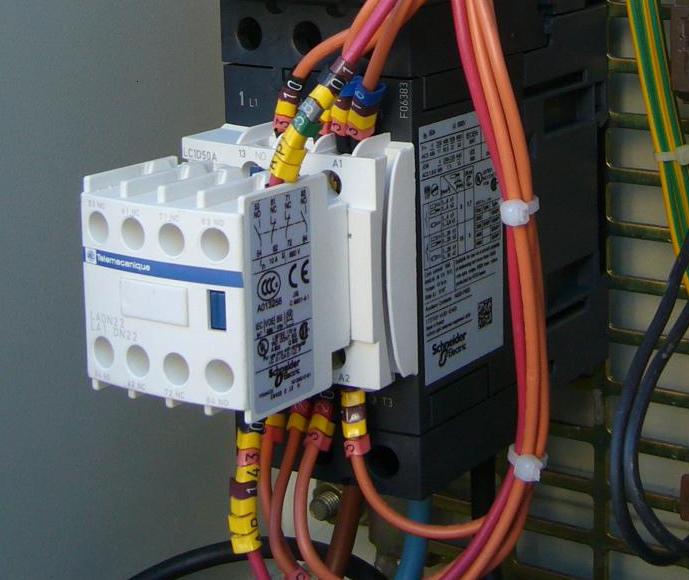
Image: AC contactor by David Shummer, released into the public domain via Wikimedia Commons.
The photograph is an AC contactor example. A high-voltage DC contactor may use different contact gaps, magnetic arc control, sealed or gas-filled chambers, terminal structures and direction-dependent ratings. Similar appearance does not establish equivalent switching capability.
Why Is High-Voltage DC Switching More Demanding?
When loaded mechanical contacts separate, an electric arc can form. In an AC circuit, current normally crosses zero every half-cycle. Under suitable device and circuit conditions, that zero crossing helps the arc extinguish. DC does not provide the same recurring natural current zero. The device must control and extinguish the arc through its contact movement, gap, material, chamber, magnetic field and surrounding circuit conditions.
This is why "30 A" or "100 A" is not a complete BESS contactor rating. A valid selection may need separate data for:
Maximum switching voltage. Use the highest charged-pack or DC-link voltage, including applicable tolerances and transients-not only the nominal battery label.
Continuous carry current. Confirm terminal and contact temperature in the real enclosure at worst ambient and duty.
Making duty. Define whether the contact closes into an uncharged capacitor, a precharged bus, a resistive load or another energized source.
Breaking duty. State the current and circuit energy at opening, including inductance, current direction and whether the converter reduces current first.
Polarity and bidirectional operation. Some magnetic arc-control arrangements have direction- or polarity-specific limits.
Electrical endurance. Use loaded switching data at conditions close to the application. Mechanical life without load is not a battery-path endurance value.
IEC 61810-10:2019 addresses high-capacity relays with additional breaking or short-circuit capability and explicitly lists electrical energy storage, solar PV, battery charge/discharge and power-electronic applications. The standard supports an important sourcing rule: a component's high-capacity claim must be tied to its documented test scope and the real circuit.
How Does DC-Link Precharge Protect Main Contacts?
An inverter normally contains DC-link capacitance. If a battery is connected directly to an uncharged capacitor bank, the initial current is limited mainly by the circuit resistance and inductance. The resulting inrush can stress battery cells, busbars, cables, connectors, fuses, capacitors and the closing contacts of the main contactor.
A common architecture adds a current-limited precharge path. A smaller relay or contactor and a resistor charge the DC-link capacitance before the main power path closes. The controller measures the relevant voltages, checks whether the precharge state is progressing correctly and closes the main contactor only after reaching a validated condition.
Texas Instruments' official application brief explains that unmanaged inrush can damage cables, connectors or fuses and can contribute to contactor pitting or welding. Its topology is an educational example, not a universal BESS wiring instruction.
|
Precharge Element |
System Role |
Qualification Question |
|---|---|---|
|
Main contactor |
Carries normal charge/discharge current after successful precharge. |
What residual voltage difference, making current and opening duty does it actually see? |
|
Precharge relay or contactor |
Connects the current-limited branch temporarily. |
Can it make the initial current and withstand full system voltage, pulse heating and repetitive duty? |
|
Precharge resistor |
Limits initial current and absorbs charging energy. |
What pulse energy, peak power, voltage, tolerance, cooling interval and failure mode apply? |
|
DC-link capacitor |
Stores energy and stabilizes the converter bus. |
What total effective capacitance, initial voltage and connected downstream capacitance are present? |
|
Voltage sensing and logic |
Determines completion, timeout, retry and safe-state response. |
Which points are measured, and what happens after an implausible reading or failed sequence? |
Useful Precharge Equations
For an ideal resistor R charging a capacitor C from a source voltage Vb:
Initial current: I(0) = Vb ÷ R
Time constant: τ = R × C
Capacitor voltage: Vc(t) = Vb × [1 − e(−t/RC)]
Stored energy: E = ½ × C × Vb2
These equations show the trade-off: lower resistance shortens the ideal charge time but increases initial current and pulse power; higher resistance reduces current but lengthens the sequence. Real systems also include battery impedance, cable inductance, contact resistance, capacitor tolerance, temperature, residual bus voltage, measurement error and controller behavior. Use the equations for screening, then validate the actual hardware and sequence.
Which Ratings Belong in a Relay or Contactor Specification?
A strong specification connects electrical duty, thermal installation, insulation, coil behavior, diagnostics, environment and life. Every rating should include its conditions. A statement such as "100 A, 1000 VDC" is incomplete until the buyer knows whether the current is continuous, making, breaking, peak or fault current and how the device was connected and protected.
|
Requirement Group |
Information to Define |
Common Mistake |
|---|---|---|
|
Voltage and insulation |
Maximum working and transient voltage, withstand requirements, clearance/creepage system, pollution and altitude. |
Buying from nominal battery voltage or a coil-to-contact test number alone. |
|
Continuous current and thermal installation |
Duty profile, ambient, enclosure airflow, conductor or busbar geometry, terminal temperature and mounting. |
Comparing catalog amperes without reproducing the supplier's thermal conditions. |
|
Making and breaking duty |
Load type, inrush, residual voltage, current at opening, inductance, direction and sequence. |
Assuming carry current covers contact closure and interruption. |
|
Coil and control |
Pickup, hold and dropout range, coil power, supply sag, driver, suppression, release time and EMC. |
Checking only nominal coil voltage. |
|
Endurance and environment |
Loaded electrical operations, cycle frequency, temperature, humidity, condensation, vibration, shock, corrosion and ingress. |
Using unloaded mechanical life as the service-life estimate. |
|
Protection and diagnostics |
Fuse/breaker, fault level, controller sequence, auxiliary contact meaning, voltage plausibility and weld detection. |
Treating the contactor or one auxiliary contact as the complete safety function. |
Thermal Rating Is a System Result
Contact resistance, terminal resistance, busbar or cable geometry, fastener condition, enclosure temperature, airflow, nearby heat sources and coil power all affect temperature rise. A device can carry its published current in a supplier test fixture and still overheat in a compact inverter cabinet. Request the test ambient, conductor or busbar condition, mounting orientation, terminal-temperature limit and derating curve, then validate instrumented samples inside the intended assembly.
Coil Suppression Changes Release Behavior
A contactor can reach the expected safe state only if its coil supply and driver remain inside the operating envelope. Define pickup at the lowest supply, hold at the highest temperature and dropout during every relevant power-loss state. Suppression can reduce driver stress and electromagnetic noise, but some methods slow current decay and contact release. Use the exact manufacturer's instructions and test the real control circuit.
AC Grid Coupling and Backup Transfer Need Separate Requirements
Grid-interactive, hybrid and backup inverters may need an AC coupling, disconnect, bypass or transfer function. These paths should be specified from the AC voltage, phase, frequency, current, power factor, load types, transition method and system-level response-not from the battery contactor requirements.

Image: PV Inverter by Simon Walker, licensed under CC BY-SA 2.0 via Wikimedia Commons. No changes made.
IEEE 1547-2018 addresses interconnection and interoperability between distributed energy resources and electric power systems, including abnormal-condition response, power quality, islanding and verification. A relay can be one physical output inside that architecture, but it does not provide IEEE 1547 performance by itself.
Backup transfer deserves special attention. The system may need source synchronization, open- or closed-transition logic, neutral switching, mechanical and electrical interlocking, load inrush management and coordinated fault clearing. Two independent relays do not automatically form a safe transfer assembly.
|
AC Function |
Engineering Question |
Selection Boundary |
|---|---|---|
|
Grid coupling or disconnect |
Which voltage, frequency, output current, power factor and abnormal-condition response apply? |
Validate the switching element together with inverter sensing, logic and market requirements. |
|
Backup transfer |
Is the transition open or closed, is synchronization required, and which loads are present? |
Use a fully interlocked and verified transfer architecture. |
|
Bypass or service path |
What fault level, manual access, isolation and operational interlock apply? |
Coordinate service switching, protection and inverter control as an assembly. |
|
Motor or transformer load |
What inrush, power factor, inductive energy and switching frequency occur? |
Resistive-load data alone is insufficient. |
How Should Battery-Side Contactor Architecture Be Reviewed?
Many high-voltage battery architectures use defined main contactors plus a separate precharge path before connecting the battery to a PCS, inverter or charger. The topology is not universal. The number and position of contactors depend on pack configuration, grounding, isolation strategy, service concept, fault analysis and applicable standards.
The purpose of multiple contactors is not simply to make a drawing look redundant. The system team must define:
Which conductor or energy path each contactor isolates.
Which device makes and breaks normal current.
What happens after an aborted or incomplete precharge.
How the BMS detects unexpected voltage, delayed movement or a welded contact.
Which fuse or breaker clears a high-current fault.
How the system reaches and verifies a safe state after control-power loss.
Dedicated high-voltage contactors may use sealed chambers, gas filling, ceramic construction or magnetic arc management. TE Connectivity's official BESS application overview shows product families specifically designed for high-voltage DC energy-storage paths. This is an example of the evidence depth a buyer should expect; it is not proof that another supplier's similarly named relay is equivalent.
Auxiliary Feedback Is Useful but Not Complete Proof
An auxiliary contact normally reports an actuator- or position-related state under defined conditions. It may not prove that every main contact is free from welding, that contact resistance is normal or that the complete bus is safely isolated. A robust diagnostic strategy can combine auxiliary feedback with bus-voltage sensing, current measurement, insulation monitoring, timing checks and controller plausibility logic.
How Do Protection and Contactor Duties Work Together?
A relay or contactor can be part of a protection architecture without being able to interrupt every available short-circuit current. Its normal task may be commanded connection and isolation, while a fuse or circuit breaker clears high fault energy. The exact behavior depends on the component, fault level, protective device, circuit inductance and controller timing.
Do not write "the contactor will trip." A conventional contactor normally follows a coil command. It is not automatically a protective trip unit.
Name the short-circuit protective device. Specify the exact fuse or breaker family, relevant interrupting rating and any manufacturer-tested combination or conditional rating.
Define the opening sequence. Determine whether the converter reduces current before the contactor opens and what happens if that control action is unavailable.
Check post-fault state. The BMS or inverter should handle disagreement between command, auxiliary feedback, measured bus voltage and current according to the validated fault matrix.
Preserve maintenance isolation. An automatically controlled contactor does not necessarily provide the visible, lockable service boundary required by the installation.
IEC 60947-4-1 distinguishes contactors and starters from the short-circuit protective device used in a coordinated assembly. Although a BESS DC path may use different product standards, the broader engineering lesson remains valuable: switching and fault interruption responsibilities must be explicitly allocated.
Which Standards Apply to Relays, Solar Inverters and BESS?
Standards apply at different levels. A relay standard establishes a component scope. A PV inverter standard evaluates a power-conversion product. An ESS standard evaluates interactions across batteries, power conversion, control, protection, enclosures and other subsystems. Do not turn one component certificate into a finished-system claim.
|
Reference |
Relevant Scope |
Does Not Prove by Itself |
|---|---|---|
|
IEC 61810-1 and IEC 61810-10 |
General relay requirements and added requirements for high-capacity relays. |
Complete PV inverter or BESS compliance. |
|
IEC 62109-1 and IEC 62109-2 |
Safety of PV power converters and particular requirements for inverter products. |
A universal approval for every storage topology or installation. |
|
IEC 62933-5-2:2025 |
Safety requirements for electrochemical grid-integrated EES across the system lifecycle. |
That one relay is suitable without system integration and testing. |
|
UL 9540 |
Evaluation of energy storage systems and equipment, including protection and control interactions. |
That separately certified components automatically form a certified ESS. |
|
IEEE 1547-2018 |
DER interconnection and interoperability with electric power systems. |
That a standalone relay is "IEEE 1547 compliant." |
UL Solutions describes UL 9540 as covering a comprehensive ESS review, including charging, discharging, protection, control and communication. This supports a safe marketing rule: state the exact relay rating, certificate and condition that can be documented; do not claim that the component alone certifies the complete solar inverter or energy storage system.
What Should a System-Level Validation Plan Include?
Component selection becomes defensible only after representative system validation. A bench check that confirms coil pickup and contact continuity does not reproduce final-enclosure heat, busbar resistance, DC-link capacitance, cable inductance, battery behavior, converter control or active protection.
Map normal, abnormal and maintenance states before testing. Include first power-up, normal shutdown, low and high battery state of charge, hot and cold ambient, low control voltage, aborted precharge, residual bus voltage, controller reset, loss of AC, safe-state opening and the permitted service sequence.
|
Validation Area |
What to Verify |
Evidence to Retain |
|---|---|---|
|
Electrical fit |
Actual voltage range, carry current, making/breaking duty, direction and load type. |
Operating points, waveforms, test plan and component revision. |
|
Precharge |
Initial current, voltage rise, completion logic, timeout, retry and main-contact closing condition. |
Sequence logs, waveforms, resistor temperature and pass/fail limits. |
|
Thermal performance |
Contact, terminal, coil and busbar temperatures at worst ambient and duty. |
Instrumented report, airflow state and cable/busbar details. |
|
Protection coordination |
Interaction among contactor, fuse/breaker, BMS and inverter command sequence. |
One-line diagram, device data, coordination evidence and system record. |
|
Diagnostics and safe state |
Feedback disagreement, weld/stuck detection, sensor fault and loss of control power. |
Fault matrix, software revision, timing traces, alarms and recovery behavior. |
High-energy DC tests require qualified personnel and a controlled facility. Capture voltage, current, coil command, auxiliary feedback, component and terminal temperature, and the relevant BMS/inverter states. Do not repeatedly power-cycle an unexplained failure; retries can increase contact damage and erase useful evidence.
Common Relay and Contactor Failure Modes
|
Observed Issue |
Possible Contributors |
Investigation Direction |
|---|---|---|
|
Welded main contact |
Uncontrolled inrush, failed precharge, wrong DC making duty, retries or abnormal fault energy. |
Preserve evidence and review the complete precharge, switching and protection sequence. |
|
Contactor will not pull in |
Low coil voltage, driver fault, BMS inhibit, wiring, connector or mechanical problem. |
Review command logs and coil voltage through approved diagnostic procedures before replacing the part. |
|
Unexpected opening |
Supply sag, coil heat, vibration, connector resistance, control logic or protection command. |
Correlate coil command, voltage, system events and temperature. |
|
Hot terminals or case |
Busbar/lug mismatch, fastener or torque problem, conductor size, high ambient, restricted airflow or overload. |
Make the system safe, inspect to the component instructions and repeat thermal validation after correction. |
|
Precharge timeout |
Open resistor/relay path, incorrect capacitance input, sensing error, residual voltage or downstream fault. |
Verify the complete RC path, voltage sensing and downstream converter state; do not bypass precharge. |
|
Intermittent auxiliary feedback |
Timing, wiring, input threshold, vibration, moisture, corrosion or device degradation. |
Check feedback semantics, debounce and voltage/current plausibility logic. |
A field failure is often an interaction failure. The corrective action should update the specification and validation plan. If the DC rating was inferred from AC data, require explicit DC making and breaking evidence. If the terminal overheated, update busbar, fastener, ambient and temperature-rise requirements. If precharge was marginal, revise the circuit and sequence requirements rather than replacing the contactor alone.
Buyer and RFQ Checklist
A useful RFQ identifies the switching location and state transition before requesting a part number. Send a controlled one-line diagram or functional block diagram where possible, then provide:
Function: battery main isolation, precharge, AC grid coupling, backup transfer, charger, auxiliary load or feedback.
Electrical maximums: maximum DC/AC voltage, maximum charged-pack voltage, continuous current, peak current, frequency and current direction.
Switching event: closing and opening current, load type, DC-link capacitance, inrush, residual voltage, circuit inductance, switching frequency and target electrical life.
Precharge data: effective capacitance, resistor concept, expected sequence, initial current and energy envelope.
Protection: fuse or breaker family, available fault current, BMS/inverter response and intended clearing sequence.
Control interface: coil voltage and tolerance, driver type, suppression method, auxiliary contacts, timing and diagnostics.
Mechanical and thermal installation: terminal type, busbar or cable, enclosure, airflow, mounting orientation, ambient temperature, vibration and altitude.
Compliance and supply: target countries, applicable standards, required certificates and reports, sample plan, change notification, traceability, MOQ and lead time.
For a second source, repeat the same qualification. A matching footprint does not establish electrical equivalence when contact construction, coil behavior, terminal geometry, derating, feedback or certificate scope changes.
Where QIANJI Power Relays Can Fit
QIANJI supplies electromechanical and solid-state relay families for clearly defined switching applications. In a solar inverter or energy storage cabinet, potential roles may include auxiliary fans, heaters, pumps, alarms, control power, low-voltage switching and other duties that match the exact model's datasheet.
Review the QIANJI power relay range for terminal- or panel-oriented switching, the QIANJI PCB relay range for board-level control and the QIANJI solid-state relay range for suitable high-cycle electronic switching.
Do not assume these categories are high-voltage BESS main-contact devices. For example, QIANJI's publicly available JQX-40F data identifies contact ratings such as 250 VAC and approximately 28–30 VDC depending on the version. Those values cannot be extended to a high-voltage battery bus. Always use the selected model's exact voltage, current, load, endurance, insulation and environmental data.
This boundary protects both buyer and supplier. It prevents an auxiliary relay from being placed in a battery-main path while allowing the correct QIANJI product to be evaluated for the lower-energy functions that exist throughout inverter and ESS equipment.
Three Example Decision Paths
Commercial BESS Battery-to-PCS Path
The system has a high-voltage battery, bidirectional charge/discharge current and substantial PCS input capacitance. Start with a dedicated high-capacity DC contactor set and an architecture-specific precharge path. Define maximum charged-pack voltage, continuous current, opening duty, current direction, fault coordination, cabinet temperature and state feedback. Qualify the component through waveforms, thermal measurements, sequence logs and protection evidence.
AC Grid-Coupling Relay in a Hybrid Inverter
The design needs a controlled AC connection and disconnection function. Define phase, voltage, frequency, output current, power factor, load inrush, transition sequence, interlocking and market requirements. Select an AC-rated device or assembly and validate it within the inverter's sensing and control architecture. Keep the battery-side DC contactor specification separate.
Auxiliary Fan or Cabinet Heater
A conventional power or PCB relay may be appropriate. A fan or pump can have motor starting current and inductive turn-off energy; a heater is closer to resistive duty; an auxiliary power supply may have capacitive input inrush. Select the relay from the exact load waveform, voltage, current, switching rate, coil interface, enclosure temperature and loaded endurance.
Frequently Asked Questions
Can an AC relay switch battery DC?
Only when the exact component documentation explicitly covers the actual DC voltage, current, load, polarity, topology and making/breaking duty. Never transfer an AC rating to a high-voltage battery or DC-link path by matching current alone.
Why does a solar inverter or BESS need precharge?
Precharge limits the inrush created when a battery connects to uncharged DC-link capacitance. A controlled relay/contactor and resistor path charges the bus before the main contactor closes. The resistor, switching device, sensors, timing and fault logic must be designed and validated together.
Does a DC contactor protect against short circuit?
Do not assume so. A contactor can participate in a coordinated protection system, but its behavior depends on the exact product, external fuse or breaker, available fault current and control sequence. Identify the protective device and documented coordination condition.
Can an SSR replace a mechanical battery contactor?
Sometimes a semiconductor switch can serve a defined function, including certain precharge approaches, but it is not a universal drop-in replacement. Compare on-state loss, cooling, off-state leakage, isolation, failure mode and the need for a verified mechanical open path.
Do all BESS designs need positive and negative main contactors?
No universal topology applies. The number and placement of main contactors depend on isolation, grounding, service concept, safety analysis, battery configuration and applicable requirements. Do not copy an EV or another BESS topology without system review.
What causes a BESS contactor to weld?
Possible contributors include uncontrolled capacitor inrush, failed or bypassed precharge, closing outside the DC making rating, repeated retries and abnormal fault energy. Preserve event data and investigate the whole circuit rather than assuming the contactor alone is defective.
Is a component IEC or UL mark enough to certify an inverter or ESS?
No. The evidence applies to the defined component scope. The finished inverter or ESS requires evaluation under the applicable product, system, installation and market requirements.
How should I choose an ESS battery-contactor current rating?
Start with maximum continuous charge/discharge current in the real enclosure. Then separately define making and breaking duty, maximum battery voltage, bidirectional current, precharge condition, terminals, thermal limits, protection coordination and loaded electrical endurance.
How often should relays or contactors be replaced?
Do not apply a universal calendar interval. Use loaded electrical-endurance data, actual operation count, duty profile, temperature, diagnostics, inspection findings, manufacturer guidance and the consequence of failure.
Final Selection Rule
For power relays in solar inverters and energy storage, begin with the state transition rather than the catalog category.
Battery or DC-link main path: require a dedicated DC contactor or high-capacity relay with explicit evidence for maximum voltage, carry current, making and breaking duty, polarity, bidirectional operation, external protection, thermal installation and endurance.
AC grid or backup path: use an AC-rated switching device or transfer assembly validated with the inverter's sensing, sequencing, interlocking and market-specific system requirements.
Precharge path: qualify the relay or contactor, resistor, capacitance, voltage sensing, timing and failure response as one controlled function.
Auxiliary path: a QIANJI power, PCB or solid-state relay may be suitable when the exact model data matches the real load and environment.
For application review, share the circuit function, one-line diagram or block diagram, maximum voltage, continuous and switching current, load type, precharge data, protection scheme, ambient conditions, expected operations and required component evidence. Contact QIANJI to discuss a model-level fit or sourcing request.
Technical References
IEC 61810-10:2019-Additional requirements for high-capacity relays
IEC 61810-1:2015-Electromechanical elementary relays
IEC 60947-4-1:2023-Electromechanical contactors and motor-starters
IEC 62109-1:2010-General safety requirements for PV power converters
IEC 62109-2:2011-Particular requirements for PV inverters
IEC 62933-5-2:2025-Safety requirements for electrochemical grid-integrated EES
IEEE 1547-2018-DER interconnection and interoperability
UL Solutions-Energy storage system testing and UL 9540 certification
Texas Instruments-Why precharge circuits are necessary in high-voltage systems