

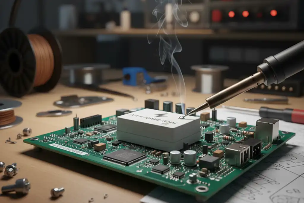
A vital piece of equipment won't turn off. The control panel shows it's switched off, but the motor, heater, or light stays powered on. This dangerous situation often happens because of one seemingly simple part: a broken relay.
The specific problem is relay contact sticking, also called contact welding. It's one of the most common and serious failure types in electrical systems. It can cause major equipment damage, create safety risks, and lead to expensive downtime.
This guide goes deeper than basic explanations. First, we'll look at the real physical reasons why contacts weld together. Then we'll give you a hands-on troubleshooting guide. Finally, we'll share solid engineering strategies for the complete solution and prevention of relay contact adhesion.
How Failure Happens
To really stop contact welding, we need to understand how two separate pieces of metal fuse together inside a relay. This process is a violent, tiny event caused by extreme heat.
The Critical Moment: Electrical Arcing
Every time a relay works, an electrical arc can form. This arc is a channel of super-hot plasma - basically a tiny welding torch hitting the contact surfaces directly.
Arcing happens at two key times. When contacts close, mechanical bouncing makes them connect and disconnect several times in milliseconds. Each separation creates a small arc. More importantly, when contacts open under load, an arc forms as they separate, trying to keep current flowing.
Main Problem: High Starting Current
The biggest cause of contact welding is high inrush current. This is the instant surge of current when a load first turns on. It can be many times higher than normal running current.
This huge, short burst of current goes through a tiny contact point as the relay closes. This energy concentration creates intense heat, melting small portions of the contact surfaces.
|
Load Type |
Typical Inrush Current Multiplier |
Duration |
|
Tungsten Lamps |
10x - 15x |
A few milliseconds |
|
Motors |
5x - 10x |
Hundreds of milliseconds |
|
Capacitive Loads / SMPS |
20x - 40x+ |
Microseconds to milliseconds |
|
Solenoids |
3x - 8x |
Tens of milliseconds |
Making Things Worse: Different Load Types
Different loads attack relay contacts in uniquely harmful ways, greatly increasing failure risk.
Capacitive loads, like those in switching power supplies, are especially bad. An uncharged capacitor acts like a short circuit for a brief moment when power is applied. This creates massive inrush current that's a primary driver of relay contact welding.
Inductive loads, like motors and solenoids, create different problems. Energy stored in the magnetic field releases when the circuit opens. This creates high voltage that keeps a powerful arc burning across opening contacts, wearing away contact material over time.
Metal Transfer and Tiny Welds
Arcing and inrush current melt metal on contact surfaces. During the brief time when both surfaces are molten, material can move from one contact to the other.
When contacts finally settle and current returns to normal, this molten metal can harden as one solid bridge, creating a tiny weld. Over many cycles, this material transfer creates "pip and crater" formation. One contact develops a sharp peak, and the other develops a matching pit. This roughens surfaces and dramatically increases the chance of future relay contact adhesion.
Hands-On Troubleshooting Guide
When a load won't turn off, correctly diagnosing a welded relay is the first step toward a permanent fix. This needs a step-by-step approach, starting with observation and moving to electrical testing.
Warning Signs
In the field, a welded relay shows several clear signs. The most obvious is that the load stays powered even when the control signal to the relay coil is removed.
You might also notice the relay's "click" sound is missing when it's told to turn off. The control system shows an open state, but the physical circuit stays closed.
Testing Steps
Before doing any hands-on testing, safety comes first. Always follow proper procedures to turn off and lock out/tag out the main power feeding the relay's load contacts.
Safety First: Make sure the main circuit breaker or disconnect supplying power to the load is OFF and locked. Check that there's no voltage at the relay's load terminals with a proper multimeter.
Check Coil Voltage: With the control circuit still active, command the relay to the OFF state. Now measure voltage across the relay's coil terminals (like A1 and A2). The reading should be 0V DC or 0V AC, or at least well below the relay's specified dropout voltage. If there's still voltage at the coil, the problem is in the control circuit, not the relay contacts.
Test Contact Continuity: With the coil confirmed off, switch your multimeter to resistance or continuity mode. Measure resistance across the normally open (NO) and common (COM) terminals that switch the load. For a healthy, open relay, the meter should read "OL" (open loop) or infinite resistance. If it reads very low resistance, typically less than 1 ohm, you've confirmed relay contact welding.
The "Tap Test": This is a last-resort test, not a repair. A gentle but firm tap on the relay housing can sometimes mechanically shock a light weld and break contacts apart. If the load turns off after a tap, you've definitely confirmed contact sticking. The relay is damaged and must be replaced immediately.
Can It Be Fixed?
The answer is absolutely no. Relay contact welding is permanent, physical damage. Contact surfaces have been melted, deformed, and changed at the metal level. Their ability to conduct electricity, their shape, and their anti-welding properties are destroyed.
Trying to "repair" a welded relay is both useless and dangerous. The goal is never to fix the failed part. The right approach is to replace the failed relay and, more importantly, investigate and fix the root cause to prevent it from happening again.
The Best Solution: Prevention
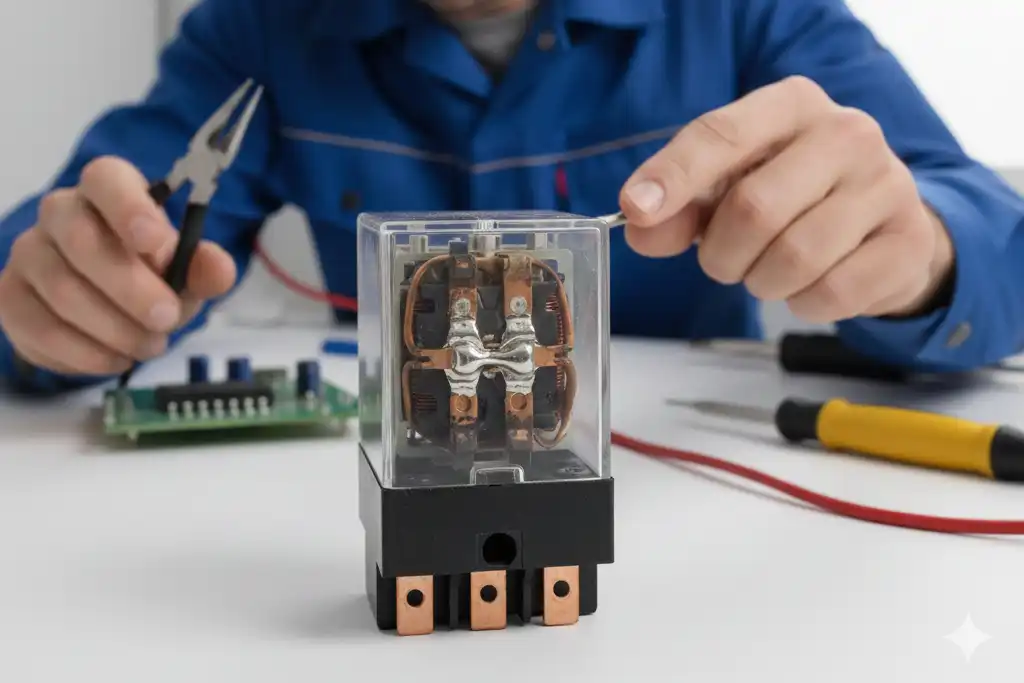
The most effective way to deal with contact sticking is to design systems where it never happens. This proactive approach combines smart circuit design with proper part selection.
Part 1: Protection Circuits
A relay contact protection circuit, often called a "snubber," is essential for managing the arc energy that destroys contacts. The goal is to provide an alternate path for the destructive energy that would otherwise damage the contacts.
For both AC and DC loads, an RC snubber circuit works very well. It has a resistor and capacitor connected in series, with this pair placed parallel to the relay contacts. When contacts open, the capacitor absorbs arc energy. When closing, the resistor limits the capacitor's discharge current. Simple formulas exist for approximation, but a good starting point is C (in microfarads) ≈ Load Current (in amps) and R (in ohms) ≈ Source Voltage.
For AC loads, a Metal Oxide Varistor (MOV) is an excellent choice. Connected parallel with the contacts, the MOV acts as a voltage clamp. During normal operation, it has very high resistance. If a high-voltage spike occurs (like from an inductive load), the MOV's resistance drops dramatically, directing energy away from contacts and stopping the arc. Choose an MOV with a clamping voltage above peak AC line voltage but below the breakdown voltage of circuit components.
For DC inductive loads, a freewheeling diode is the simplest and most effective solution. Placed parallel with the inductive load (like a solenoid coil or DC motor), the diode is reverse-biased during normal operation. When the relay opens, the collapsing magnetic field creates current that safely circulates through the diode and load until it fades away, preventing a high-voltage arc across relay contacts. The diode's cathode must connect to the positive side of the switched voltage.
Part 2: System-Level Design
Circuit protection is only half the solution. Strong, long-term prevention needs thoughtful system-level design and part selection.
A critical idea is derating. This means operating a relay well below its maximum rating to build in a significant safety margin. A relay rated for a "10A resistive load" isn't suitable for a 10A motor load. The high inrush current relay failure mechanism demands a much more careful approach. As a general rule, for high-inrush loads like motors or power supplies, we often reduce the relay's current-handling ability by 50-80% as a starting point.
Choosing the right contact material is crucial for preventing sticking. Different materials have very different properties when exposed to arcing and high currents.
|
Material |
Pros |
Cons |
Best For |
|
Silver (Ag) |
High conductivity |
Prone to sulfidation, soft |
General purpose, resistive loads |
|
Silver-Tin-Oxide (AgSnO2) |
Excellent anti-welding properties, environmentally friendly |
Higher cost, slightly higher resistance |
High inrush, capacitive, DC loads |
|
Silver-Cadmium-Oxide (AgCdO) |
Good anti-welding (legacy) |
Environmental concerns (Cadmium) |
Phasing out, formerly for motors |
|
Tungsten (W) |
Very high melting point, arc-resistant |
High contact resistance, brittle |
High voltage, high inrush (e.g., lamp loads) |
Finally, for AC loads, consider using zero-cross switching. This can be done with a solid-state relay (SSR) or a smart electromechanical relay with a control circuit. This technique ensures relay contacts only close when the AC voltage waveform crosses near zero volts. Turning on a load at near-zero voltage dramatically reduces or even eliminates inrush current, especially for capacitive and resistive loads, making it a powerful tool against contact welding.
Real Example: Pump System
To show these principles, consider a real-world case involving repeated failure in an industrial water treatment facility.
The Problem
A 3-phase pump, controlled by a large electromechanical relay (a contactor), was failing every two to three months. The failure was always the same: maintenance would find the contactor's main contacts welded shut, causing the pump to run continuously and overflow a holding tank.
The Analysis
Our testing process started by confirming the failure. With the system locked out, a multimeter across the de-energized contactor's output terminals showed near-zero ohms of resistance. The contacts were indeed welded.
To understand the root cause, we used a clamp meter with peak-hold or inrush function on a replacement contactor. The pump's nameplate showed a full-load running current of 12A. However, the meter revealed a startup inrush current spike of over 100A that lasted for several AC cycles.
The existing contactor was a general-purpose model rated for 20A (AC-3 motor load) with standard Silver-Nickel (AgNi) contacts. While the 20A rating seemed enough for a 12A load on paper, it clearly couldn't handle the repeated 100A inrush current, which was melting and welding the contacts.
The Fix
A two-part solution and prevention of relay contact adhesion strategy was put in place.
First, the component was upgraded. The general-purpose contactor was replaced with a heavy-duty contactor of the same current rating but with a more severe AC-4 duty cycle rating. Crucially, we specified a model with Silver-Tin-Oxide (AgSnO2) contacts, which are specifically designed for superior anti-welding performance in high-inrush applications.
Second, we added circuit protection. Even with the better contactor, we installed properly sized RC snubber networks across each of the three-phase contacts. This helped manage arc energy created during pump shutdown, protecting the new contacts from long-term wear.
The Result
The results were clear. The system, which had failed every quarter, was monitored for the next 18 months. In that time, there were zero contactor failures. The root cause - severely underestimating inrush current and using inadequate contact material - was successfully identified and fixed, moving the system from chronic failure to high reliability.
Conclusion: Smart Design
Relay contact sticking isn't random or unpredictable. It's a predictable failure caused by the basic physics of heat generated by inrush current and electrical arcing. Fixing it requires going beyond simply replacing the failed part.
A successful, long-term solution rests on a proactive design approach built on three pillars. By understanding the true nature of the load, protecting contacts from arc energy, and selecting components with appropriate materials and derating, you can engineer reliability into your system from the start.
Understand the Load: Always measure or accurately estimate inrush current, not just steady-state current.
Protect the Contacts: Use appropriate protection circuits like snubbers, varistors, or freewheeling diodes to manage arc energy.
Select and Derate Wisely: Choose the correct contact material for the load type and always apply a conservative derating factor.
Investing a small amount of time in proper analysis and prevention is far more efficient and cost-effective than dealing with emergency downtime, equipment damage, and safety risks caused by a welded relay.
Error Correction and Calibration Methods for Time Relays Guide 2025
How to Achieve Energy-saving Control Using a Time Relay Guide 2025
The Role of Time Relays in Fire Protection Systems: Critical Guide 2025
Circuit Design and Principle Analysis of Time Relays: 2025 Guide