


Relay contact bounce is the brief, unwanted opening and closing that occurs after mechanical contacts first touch or reclose. The armature, springs and contact surfaces still contain mechanical energy, so they can rebound several times before settling. A fast PLC, counter or microcontroller may read one relay operation as several events.
The right fix depends on the actual problem. Use a stable coil drive and suitable relay to control the mechanical motion. Use hardware or software debouncing to prevent false logic events. Use the correct load-protection circuit to reduce arcing, inrush and contact wear. These three layers support each other, but they are not interchangeable.
Do not start with a universal 5 ms, 10 ms or 20 ms timer. Relay construction, coil voltage, contact form, temperature, load, mounting, suppression and aging all affect the waveform. Measure both operating and release transitions on representative samples, then choose a documented margin that still meets response-time and safety requirements.
Safety boundary: The low-voltage measurement methods in this guide do not authorize probing mains, battery packs, motor drives or other high-energy circuits with a grounded bench oscilloscope. High-energy contact tests require qualified personnel, correctly rated isolated or differential instruments and the equipment's electrical-safety procedure.
Relay Bounce, Chatter and Noise: Quick Diagnosis
|
Observed Pattern |
Likely Mechanism |
Correct First Action |
|---|---|---|
|
Several rapid edges immediately after one valid contact transition, followed by a stable state. |
Contact bounce: mechanical rebound and vibration after impact. |
Measure the bounce distribution; improve relay/drive/mounting and debounce the receiving input. |
|
Repeated operation, buzzing or cycling that continues beyond one short transition. |
Chatter: unstable coil voltage, supply collapse, ripple, vibration or feedback behavior. |
Measure voltage at the coil pins under worst load and temperature; correct the drive or mechanical cause. |
|
Sharp high-frequency events during power-load make or break. |
Arcing or load transient: inductance, capacitance, inrush or high DC interruption energy. |
Verify relay load capability and design the appropriate snubber, clamp, inrush or switching strategy. |
|
Narrow spikes with no matching armature movement, often on long or high-impedance wiring. |
Electrical noise: coupling, ground shift, ESD, coil kickback or load switching. |
Correlate channels, then improve grounding, routing, shielding, protection and filtering. |
Three-layer rule: reduce abnormal mechanical motion, prevent remaining bounce from becoming false logic, and protect the physical contacts from load energy. A longer software delay can hide chatter from the controller while the relay continues to damage itself.
1. What Does Relay Contact Bounce Look Like?
An ideal normally open contact changes once from open to closed. A real electromechanical contact may close, reopen for a few microseconds or milliseconds, close again and repeat until contact pressure and armature position become stable. On a scope, the contact voltage appears as a cluster of complete or partial transitions instead of one clean edge.
OMRON's general-purpose relay technical guide defines bounce as undesirable intermittent switching when contacts turn on or off. It also distinguishes operating bounce for normally open contacts from release bounce when normally closed contacts reclose. Panasonic's relay terminology describes the same physical cause: collision of moving metal parts or contacts during relay operation or release.

This public-domain image shows bounce from a latching mechanical switch, not a relay qualification test. Relay contacts create the same type of repeated-edge problem, but the displayed duration must not be reused as a relay specification. Image: Switch bounce by Tomoldbury via Wikimedia Commons.
Operate time is not necessarily stable-contact time
A catalog may state that a relay operates in a certain time, yet the signal may still be bouncing after the first contact event. OMRON and Panasonic both state in their general terminology that operate and release time exclude bounce. Other manufacturers or special relay series may use a timing definition that includes it. Read the note attached to the exact value.
|
Timing Term |
Practical Meaning |
Design Consequence |
|---|---|---|
|
Operate time |
From applying coil power to the specified normally open contact operation; definition is model-specific. |
The first contact event may be on time even though the signal is not yet stable. |
|
Operating bounce time |
From initial NO closure until unwanted opening and closing has ended under stated conditions. |
Needed when a controller must know when the NO state is trustworthy. |
|
Release time |
From removing coil power to the specified release or NC reclosure event. |
Coil suppression can extend this time without changing the original operate time. |
|
Release bounce time |
Intermittent switching associated with NC contact reclosure. |
Important for changeover feedback and cannot be assumed equal to NO bounce. |
|
System settling time |
Command-to-accepted-state interval defined by the equipment designer. |
May include relay motion, bounce, filter delay, sampling phase and safety margin. |
2. Why Do Mechanical Relay Contacts Bounce?
A relay converts magnetic force into movement. When coil current becomes high enough, the armature accelerates toward the magnetic core and moves the contact spring. The moving contact strikes the fixed contact, but neither part is perfectly inelastic. Springs flex, contact tips deform microscopically, the armature can rebound from its stop and the assembly vibrates. Contact force and damping eventually remove the energy.
OMRON notes that bounce is influenced by armature speed, the quality of moving parts and contact-spring elasticity. Relay designers use spring, contact and stopper geometry to damp the impact. The user cannot normally adjust those internal details, but coil waveform, mounting, vibration, load and temperature can change how the same design behaves.
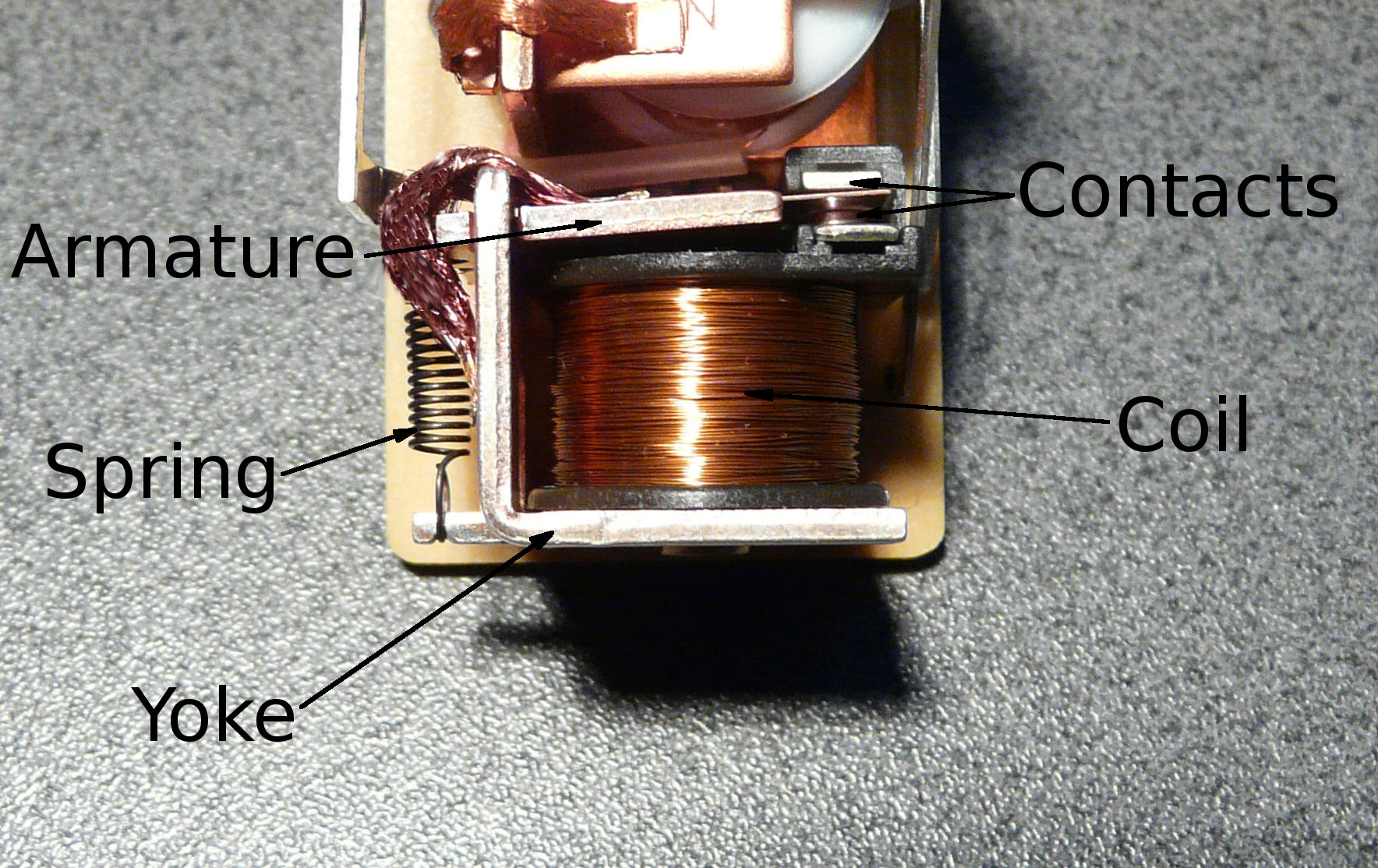
The coil accelerates the armature, while the spring and contact system determine how impact energy is absorbed. This labeled photograph is explanatory, not a dimensional drawing for a particular QIANJI model. Image: Relay Parts by David Boettcher, released into the public domain via Wikimedia Commons.
Factors that change the waveform
- Armature velocity and coil overdrive: more magnetic force can shorten operate time but also increase impact energy. Excess voltage is not a free speed improvement.
- Contact spring, mass and geometry: stiffness, travel, overtravel, contact mass and stopper design shape rebound frequency and duration.
- Slow or marginal coil drive: a slow voltage ramp or hot-coil voltage drop can produce low contact pressure, incomplete seating or chatter.
- Coil suppression: the clamp controls how quickly magnetic energy decays and therefore changes release speed and NO/NC dynamics.
- Load waveform: inrush, inductive energy, capacitance and DC arcing can interact with the contacts during every rebound.
- Mounting and environment: PCB flex, a loose socket, machine vibration, magnetic coupling, temperature, contamination and aging all matter.
Panasonic's relay cautions emphasize that coil voltage, ambient temperature and practical operating conditions affect operate, release and bounce timing. Test the finished assembly rather than treating a quiet room-temperature bench result as final evidence.
3. Why Relay Bounce Matters to Logic and Power Circuits
Logic inputs can count one operation several times
Mechanical contacts move much more slowly than digital logic reacts. Texas Instruments notes in its Schmitt-trigger debounce application brief that physical switch bounce can last hundreds of microseconds while logic devices respond in nanoseconds. The same speed mismatch exists when relay feedback drives a counter, interrupt, step input, event logger or high-speed PLC channel.
A standard input filter may prevent multiple program events, but the interface must also tolerate cable noise, ESD, overvoltage, leakage and different ground potentials. A software timer connected to an unprotected GPIO is not a complete industrial input design.
Low-level contacts may show unstable resistance
At very small currents, contact films or contamination may not be electrically disturbed. Bounce can appear as changing resistance rather than perfect full-voltage edges, particularly with high-impedance receivers. Choose contact material and structure for the published minimum switching load, and verify the actual atmosphere, frequency and acceptable resistance change.
Power bounce can accelerate arcing and wear
When current is present, every separation can initiate an arc and every reclosure can remake the load's inrush. The result can include EMI, erosion, material transfer, rising resistance or welding. Severity depends on AC or DC, voltage, source impedance, inductance, capacitance, phase angle, contact material and opening speed.
Logic debouncing prevents false decisions; it does not reduce the current flowing through a bouncing power contact. If a motor, solenoid, lamp, transformer or capacitive power supply is damaging contacts, increasing a PLC filter will make the indication cleaner while leaving the physical stress unchanged.
4. How Long Does Relay Contact Bounce Last?
There is no universal "normal" bounce time. Some data sheets publish a separate maximum operating or release bounce. Some state operate time "excluding bounce." Some special or reed-relay sheets publish an operate time "including bounce." The number is useful only with its definition, coil voltage, temperature, contact test condition and pass/fail threshold.
A measured example from another relay cannot set your debounce interval. Even one relay may produce a distribution from cycle to cycle. Different samples, production lots, temperature, vibration, contact load and life exposure can shift the tail of that distribution.
A defensible timing budget contains:
- the relevant operate or release time;
- measured or guaranteed bounce for the correct edge and contact form;
- hardware-filter or software stable-state delay;
- sampling and processing tolerance;
- a documented margin for parts, voltage, temperature, mounting, load and aging;
- the maximum response time permitted by the equipment and risk analysis.
Filtering for an unnecessarily long time can hide valid short pulses, delay an interlock or make troubleshooting harder. Filtering for too little time creates false events. Measurement connects the two limits.
5. How to Measure Relay Contact Bounce Safely
For signal and logic characterization, use an isolated low-voltage test whenever possible. Drive the relay coil with the intended circuit. Connect the contact to a current-limited pull-up or pull-down that represents the actual receiver. Capture coil-pin voltage and contact voltage on separate channels so contact motion can be related to the command.
Define the test before collecting attractive screenshots. If different engineers use different thresholds, pulse-width limits or stable-time definitions, their bounce numbers cannot be compared.
|
Measurement |
Definition to Record |
Why It Matters |
|---|---|---|
|
Operating and release bounce |
First transition, upper/lower voltage thresholds, minimum pulse width and required stable interval. |
Creates a repeatable end-of-bounce rule for both directions. |
|
Contact voltage and current |
Actual pull-up, wetting or load current and make/break voltage. |
A 1 mA logic test does not reproduce a power-load arc or inrush event. |
|
Coil voltage and current |
Voltage at relay pins, driver drop, ripple, supply dip and suppression-clamp behavior. |
Separates normal bounce from marginal drive or chatter. |
|
Command-to-stable state |
Total time from coil command to accepted system state. |
Verifies the real sequence timing after filtering and sampling. |
|
Test population |
Sample count, cycles, lots, temperature, voltage, load, mounting, vibration and aging state. |
Shows whether the selected limit covers a distribution rather than one sample. |
A repeatable test sequence
- Record the full relay code, coil driver, suppression, contact circuit, receiver thresholds and mounting.
- Capture normally open operation and release; capture normally closed reclosure when the application uses it.
- Test enough cycles and units to see variation rather than selecting one clean waveform.
- Sweep minimum, nominal and maximum permitted coil voltage plus cold and hot conditions.
- Repeat with the intended PCB/socket, enclosure, load, wiring and relevant vibration.
- Include aged or endurance samples when timing affects production release, diagnostics or safety.
- Set a maximum bounce, maximum settle time and no-chatter criterion, then document the margin.
Retest when the relay, contact material, coil driver, suppression, PCB, socket, harness, load or firmware filter changes. Each can invalidate the original timing margin.
6. How to Reduce Relay Contact Bounce Problems
The best method is chosen by the failure mechanism. The following table separates source reduction, logic filtering and load protection.
|
Method |
Best Use |
Critical Limitation |
|---|---|---|
|
Correct relay and coil drive |
Source reduction for unstable, slow or excessive mechanical motion. |
Short bounce alone does not prove the relay meets load, insulation or life requirements. |
|
RC plus Schmitt trigger |
One or several protected logic inputs needing a clean edge. |
Tolerance changes delay; it does not protect power contacts from load energy. |
|
S-R latch |
Break-before-make changeover feedback where very low added delay is useful. |
Requires the correct contact form, input protection and forbidden-state analysis. |
|
PLC or software stable-state filter |
Configurable channels, diagnostics and state-machine integration. |
Adds latency and cannot repair arcing, EMI, overvoltage or physical chatter. |
|
Load snubber, clamp or inrush control |
Inductive, capacitive, lamp, motor, transformer or high-stress loads. |
Not a logic debounce method; leakage, release time and failure behavior must be checked. |
|
Reed relay, SSR or semiconductor switch |
Timing or cycle-rate requirements that a conventional EMR cannot meet. |
Each alternative has different current, leakage, heat, isolation, surge and failure limits. |
Fix the relay and coil drive first
Apply the rated or permitted coil voltage with a clean transition unless the manufacturer specifies another profile. Measure at the relay pins, including transistor drop, wiring loss, shared-supply startup and hot-coil resistance. Avoid a slow ramp through the operate region and do not overdrive simply to gain speed.
If PWM hold-current reduction is used, provide the specified pull-in pulse first. Validate frequency, duty, ripple and suppression so the armature remains fully seated. Also control socket looseness, PCB flex, external magnetic fields, mounting orientation and machine vibration.
Use an RC network with a Schmitt-trigger input
An RC low-pass filter requires the contact to remain in the new state long enough for the capacitor voltage to cross a threshold. A Schmitt trigger adds hysteresis-different rising and falling thresholds-and converts the slow capacitor waveform into one clean logic edge. Do not assume an ordinary CMOS input safely accepts a slow edge unless its data sheet permits it.
The nominal time constant is τ = R × C. For a rising capacitor voltage, an initial model is t = -RC × ln(1 - VTH+/VCC). Real delay also depends on resistor/capacitor tolerances, input thresholds, leakage, contact resistance, protection devices, temperature and capacitor bias.
Illustrative calculation only: with 5 V, 47 kΩ, 0.22 µF and a 3 V rising threshold, the ideal RC threshold delay is about 9.5 ms. A ±5% resistor and ±20% capacitor already create a wide timing range before threshold and temperature variation. Calculate both edges and verify the final circuit; do not copy this example as a QIANJI relay recommendation.
Use stable-state software, not a one-time blind delay
A robust digital debounce accepts a new state only after the raw input has remained continuously there for the full interval. If it returns to the old state, cancel or restart the candidate timer. Keep the last accepted output until the new state qualifies, and log an excessive transition time or edge count as a possible chatter, noise or relay fault.
- Sample or timestamp the raw input deterministically.
- When it differs from the accepted state, start a candidate-state timer.
- Restart the timer if the raw state changes again.
- Accept the change only after continuous stability for the validated interval.
- Apply the required logic to both edges and verify the sampling-phase tolerance.
Confirm whether a PLC filter affects ordinary inputs, high-speed counter channels, ON transitions, OFF transitions or both. Do not add an undocumented delay to a safety or protection input.
Use an S-R latch when the contact form supports it
A break-before-make SPDT contact can drive the set and reset inputs of a latch. After one throw changes the output, bounce that briefly releases the same throw returns the latch to its hold state rather than reversing the output. Analog Devices' relay-interface guide shows latch, RC/Schmitt and protected debounce approaches.
The design must prevent the forbidden latch state and confirm that the relay is break-before-make. Input protection, wire faults, common-mode voltage and insulation still require analysis.
7. Coil Suppression Changes Release Dynamics
When a DC coil is switched off, its collapsing magnetic field creates a voltage transient. A reverse diode is a common low-voltage clamp, but it recirculates current and slows magnetic decay. That can lengthen release time and change the speed at which normally open contacts separate and normally closed contacts reclose.
TE Connectivity's DC relay coil-suppression application note explains that a diode-plus-zener arrangement can preserve faster release for the normally open contact behavior discussed there. It also notes that a slower armature caused by a simple diode may reduce NC reclosure bounce in some relays. Therefore, "does a flyback diode reduce bounce?" has no single answer without the contact duty and relay model.
|
Coil Clamp |
Typical Dynamic Effect |
What to Verify |
|---|---|---|
|
Flyback diode |
Low clamp voltage, slow current decay and longer release. |
NO opening speed/life, NC closure bounce, polarity, energy and hot-coil behavior. |
|
Diode plus zener or TVS |
Higher controlled clamp and faster decay than a plain diode. |
Driver voltage margin, clamp tolerance, repetitive energy, EMC and manufacturer guidance. |
|
Resistor or RC network |
Can provide intermediate damping and may avoid polarity dependence. |
Power, peak voltage, release dynamics, tolerance and failure modes. |
Never optimize only the transistor clamp voltage. Validate coil-current decay, release time, both contact edges and actual electrical life.
8. Load Protection Is Not the Same as Debouncing
An RC input filter protects a logic decision from short pulses. A contact or load snubber controls switching energy. Both can contain resistors and capacitors, but they operate at different voltages, currents and risk levels.
Depending on AC/DC voltage, current, load type and release-time needs, a design may use a diode, diode-zener, TVS, varistor or RC snubber for an inductive load. A capacitive input or lamp may require series impedance, pre-charge, zero-cross control or another switching device. These measures can reduce the energy present during each rebound, but they do not stop the mechanical impact or guarantee one logic transition.
Panasonic warns that an incorrect contact-protection circuit can create new problems. For example, a capacitor intended to reduce opening arcing can discharge as a large closing current and increase welding risk. Verify leakage, placement, component ratings, load release behavior, switching phase and fault consequences on the real equipment.
9. Should You Select a Different Relay Technology?
For low-level feedback, look for a suitable minimum switching load, contact material, bifurcated or twin contacts where appropriate, stable contact resistance, sealing and separately defined bounce data. For power loads, start with real make/break current, inrush, DC arc capability, contact material and life evidence before optimizing milliseconds.
QIANJI's current PCB relay category can be used as a starting point for electromechanical options, but selection must be based on the exact data sheet and application. Ask for the complete coil/contact code and timing definitions.
A reed relay may offer fast low-level switching, but it remains mechanical and can still bounce. A solid-state relay has no moving contact and therefore no mechanical contact bounce. However, an SSR introduces off-state leakage, on-state voltage drop, heat, output-type, surge, minimum-load, zero-cross/random-turn-on and failure-mode considerations. Review QIANJI's solid-state relay category only when those tradeoffs suit the load and safety design.
10. Troubleshooting Relay Bounce and Chatter
|
Symptom |
Confirmation |
Corrective Direction |
|---|---|---|
|
One coil command creates several counts |
Capture raw contact and controller input; compare edge timestamps. |
Add validated hardware/software debounce and verify both edges plus minimum valid pulse. |
|
Relay buzzes during load startup |
Measure coil-pin voltage/current during inrush and at hot temperature. |
Correct supply, wiring, driver, sequencing or vibration; do not hide the cycling with a timer. |
|
Waveform changed after replacing a diode or TVS |
Compare coil-current decay, clamp voltage, release time and NO/NC waveforms. |
Select suppression with relay/contact-duty guidance and retest load life. |
|
False input remains after increasing debounce |
Correlate coil, raw contact, receiver pin, ground and load current. |
Fix EMI, ESD, grounding, leakage, wiring or physical chatter instead of adding more delay. |
|
Contacts are blackened, hot or welded |
Measure actual inrush/make/break waveform and temperature in a qualified setup. |
Correct relay rating, load suppression/inrush, switching rate, terminal or wiring; replace damaged parts. |
|
Only installed units show extra transitions |
Compare free relay, assembled PCB/socket, enclosure and operating machine. |
Improve mounting, support, spacing, retention or vibration performance. |
11. Production Validation Checklist
- Design qualification: record bounce distributions, coil-pin waveforms, actual load current, filter calculations and worst-case system timing.
- Incoming inspection: confirm part number, date/lot, markings, coil characteristics, packaging condition and certificate traceability.
- Assembly process: control soldering, cleaning, socket retention, terminal stress, polarity, spacing, flux and vibration-sensitive handling.
- End-of-line test: verify operate/release function, accepted-state timing and a diagnostic for no-operation or excessive transition time.
- Reliability validation: switch the real load waveform through the required temperature, supply, vibration and suppression conditions.
- Change control: review changes to relay, driver, clamp, PCB, firmware filter, load, harness, socket and enclosure.
IEC's record for IEC 61810-1:2015+AMD1:2019 provides the general and safety requirements framework for electromechanical elementary relays within its scope. The finished product can require additional equipment standards and application testing. A standard designation does not create a universal bounce limit or debounce interval.
12. What to Ask for in a Relay RFQ
If bounce or settling time matters, do not request only "operate time." Ask the supplier to identify which values are guaranteed, typical or reference-only and to provide the test conditions.
|
RFQ Area |
Information to Provide |
Evidence to Request |
|---|---|---|
|
Relay identity |
Series, full code, contact form/poles, latching or monostable, PCB/socket and terminal version. |
Current drawing, data sheet, sample/lot identity and approved alternates. |
|
Timing |
Required operate, release, operating bounce, release bounce and total settle time. |
Guaranteed vs typical status, thresholds, temperature, coil voltage, current and bounce definition. |
|
Coil and suppression |
Nominal supply, driver, ripple, pull-in/hold method, clamp and hot ambient. |
Must-operate/release limits, hot-coil guidance and approved suppression with timing/life effects. |
|
Contact load |
AC/DC voltage, steady current, inrush, load type, switching frequency and expected life. |
Relevant load ratings, life data, contact material/minimum load and protection recommendations. |
|
Environment and supply |
Temperature, vibration, contamination, mounting, certification market and annual quantity. |
Qualification scope, change notification, traceability, failure analysis and continuity plan. |
Send these conditions through the QIANJI inquiry page. The most useful question is: "For this exact relay code, what are the operating and release bounce limits, under which coil, temperature, contact-current, suppression, mounting and threshold conditions, and what must be revalidated for our real load?"
Frequently Asked Questions
What is relay contact bounce?
It is the rapid, unwanted opening and closing that occurs briefly after mechanical contacts first touch or reclose. The armature, spring and contact surfaces rebound before settling, which can create several electrical edges from one relay command.
Is contact bounce the same as relay chatter?
No. Bounce is a short cluster around one valid transition. Chatter is repeated or sustained unwanted operation, often caused by unstable coil voltage, supply drop, ripple, vibration or a feedback loop. A filter can hide chatter without stopping physical damage.
How many milliseconds of relay bounce are normal?
There is no universal value. Data-sheet definitions differ, and timing changes with relay design, coil voltage, temperature, load, mounting, suppression and aging. Use the exact guaranteed data where available and measure the application.
Does relay operate time include contact bounce?
Often it does not. OMRON and Panasonic general terminology excludes bounce from operate and release time, but some specialized data sheets use an "including bounce" definition. Read the note beside the exact value.
What debounce time should I use?
Choose it from measured worst-credible bounce plus a documented margin. Test both edges across samples, coil voltage, temperature, load, suppression, mounting, vibration and aging while confirming the maximum permitted system response time.
Does a flyback diode reduce contact bounce?
It changes release dynamics, not bounce in one universal direction. A diode slows coil-current decay and armature release. That can hurt normally open release performance in some cases while reducing normally closed reclosure impact in others. Validate the exact relay and contact duty.
Will an RC snubber stop mechanical contact bounce?
No. A correctly designed power snubber can reduce arcing and transients. An RC network on a logic input can filter bounce pulses. Neither stops the mechanical parts from rebounding, and the two circuits have different ratings and risks.
Can contact bounce damage relay contacts?
Yes, particularly when meaningful current or voltage is present. Repeated make and break events can add arcing, inrush, wear, material transfer, EMI or welding risk. Logic debouncing does not remove that energy.
Do solid-state relays have contact bounce?
No mechanical contact bounce occurs because an SSR has no moving contacts. An SSR is not automatically interchangeable with an electromechanical relay; leakage, voltage drop, heat, surge behavior, output topology and failure mode must be evaluated.
How do I separate bounce from electrical noise?
Capture coil voltage, raw contact voltage, controller input and load current together. Bounce forms a short cluster immediately after contact motion. Noise can appear without corresponding movement, while chatter correlates with repeated coil dropout or vibration.
Final Recommendation
Treat relay contact bounce as a system problem with a mechanical source. First confirm that the relay receives a clean, correctly sized coil drive and is not chattering because of voltage drop, slow ramps, vibration or marginal hot-coil force. Then measure raw operating and release waveforms over enough samples and conditions to understand the worst credible behavior.
Choose the mitigation layer that matches the problem: a suitable relay and stable drive for mechanical behavior, a protected hardware or software filter for logic integrity, and a validated suppression or inrush strategy for contact-load energy. If the remaining timing or lifecycle cannot meet the requirement, evaluate another relay construction or an SSR with full consideration of its different electrical behavior.
Technical References
- OMRON Industrial Automation - Further Information of General Purpose Relays
- Panasonic Industry - Relay Terminology
- Panasonic Industry - Relays Cautions for Use
- TE Connectivity - Relay Coil Suppression with DC Relays
- Texas Instruments - SCEA094 Switch Debounce Application Brief
- Analog Devices - Interfacing Switches and Relays to the Real World in Real Time
- IEC 61810-1:2015+AMD1:2019 - Electromechanical elementary relays
Engineering note: Verify the latest data sheet, guaranteed versus typical timing, certification scope, test definition and application standard for the exact relay code. Safety-related feedback and filtering require a qualified system hazard and diagnostic analysis.