

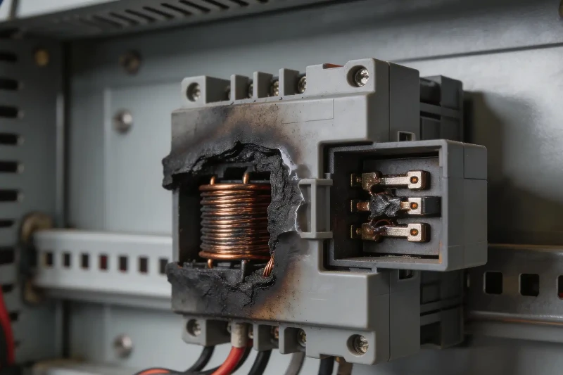
Analyze a relay field return by preserving the original assembly, documenting the exact symptom and service history, reproducing the failure in circuit where safe, checking the coil drive and load path, and using non-destructive examination before any teardown. A relay found on a failed board is not automatically the root cause. The defensible conclusion is the one that connects an observed failure mode to a physical mechanism and then to evidence from the actual equipment.
The seven-step field-return workflow
- Make the unit safe and quarantine the as-returned evidence.
- Record the symptom, relay identity, circuit, load, environment, and service timeline.
- Verify the reported failure in the complete assembly when safe and practical.
- Separate the coil drive, relay mechanism, contacts, load, PCB, and connections.
- Use controlled off-board and non-destructive tests to narrow the mechanism.
- Open the relay only when teardown can answer a defined question.
- Confirm the causal chain and validate a corrective action under representative conditions.
This guide is for quality engineers, OEM design teams, reliability laboratories, field-service leaders, relay suppliers, and sourcing teams handling RMA investigations. It is not a substitute for electrical-safety procedures or a qualified failure-analysis laboratory. Before comparing results, confirm the exact relay family and ordering code; QIANJI's current relay product range and PCB relay category provide a starting point, but the applicable datasheet and approved specification must control the investigation.
What a Relay Failure Analysis Must Prove
A useful field-return analysis answers four different questions. Was the customer symptom reproduced? Is the relay outside an applicable specification or function? What physical or electrical mechanism produced that state? What initiating condition created the mechanism in service?
| Conclusion level | What it means | Evidence required |
|---|---|---|
| Symptom confirmed | The reported behavior was observed on the returned unit or a controlled replica. | Documented test setup, operating condition, result, repeatability, and sample state. |
| Relay nonconformance confirmed | The relay fails a relevant specification or functional test after excluding setup error. | Exact part identity, valid test method, coil condition, contact load, limits, and comparison result. |
| Failure mechanism identified | Physical or electrical evidence explains the failed state. | Consistent signatures such as welding, open winding, contamination, corrosion, or mechanical obstruction. |
| Root cause confirmed | A specific initiating field, design, process, or material condition is shown to have created the mechanism. | Returned-part and system evidence, replication or strong correlation, and elimination of credible alternatives. |
Reporting rule: "The contacts are welded" describes an observed state. "A relay manufacturing defect caused the contacts to weld" is a root-cause claim. Do not write the second statement unless evidence links the internal condition to manufacture and excludes application stresses such as inrush, short circuit, chatter, or overload.
If the evidence supports only a hypothesis, label it as suspected. If essential field data or representative samples are missing, report the result as inconclusive and state what would be needed to continue. A careful inconclusive report is more useful than an unsupported defect label.
First Rule: Preserve the As-Returned Evidence
The first person who receives the returned equipment can determine whether the later investigation is possible. Repeated cycling, cleaning, de-soldering, replacing a fuse, opening a relay cover, or pressing probes into terminals may alter an intermittent fault or erase contamination and heat evidence.
Begin with product-specific lockout, discharge, ESD, stored-energy, and high-voltage procedures. Do not energize visibly damaged equipment only to obtain a quick result. Photograph the complete unit before moving parts: enclosure, connectors, wiring, relay markings, orientation, PCB, fuses, terminals, heat patterns, contamination, nearby components, and any customer modifications.
Assign a return ID and record who handled the unit, when, where it was stored, and what each person changed. Note product serial number, board and firmware revision, relay manufacturer, full ordering code, date or lot markings, installation location, and packaging condition. If the customer returned only a loose relay, record that limitation-the missing board, load path, solder joints, and wiring are part of the lost evidence.
| Capture at intake | Decision value | Common evidence loss |
|---|---|---|
| As-returned photos and labels | Preserves orientation, heat, contamination, lot data, terminals, and board revision | Cleaning or removing the relay before documentation |
| Customer symptom and event timeline | Turns "not working" into a testable operating event | Accepting a one-word defect code without load or command state |
| Load and switching history | Reveals inrush, overload, short circuit, frequency, and suppression conditions | Comparing only steady current with a headline relay rating |
| Coil drive and power data | Reveals drop-out, chatter, ripple, surge, or polarity problems | Testing only the loose relay and never the in-circuit waveform |
| Environment and process history | Connects failures to moisture, gases, flux, cleaning, coating, vibration, or rework | Assuming a clean laboratory sample represents its service history |
Build the RMA Case File Before Testing
A compact case file makes returns comparable across customers, lots, sites, and revisions. Record the installed population, number failed, time in service, event frequency, operating mode, prior repair, firmware or circuit changes, and whether the issue appeared at start-up, maximum load, temperature transition, cleaning, vibration, or a power-quality event. "Unknown" is a valid data value; an assumption presented as fact is not.
Request a comparison set when possible:
- the unmodified failed assembly rather than only the removed relay;
- a known-good assembly from the same revision and similar service age;
- an unused relay from the same lot when available;
- the schematic section showing coil drive, suppression, contacts, load, supply, and protection;
- scope captures, logs, alarm history, measured load inrush, coil voltage, switching frequency, and environmental data.
A new relay from another lot is a useful reference, but it does not prove the returned unit was defective at manufacture. The strongest comparison controls part revision, equipment revision, service age, load, and environment.
Use a Least-Invasive-to-Most-Invasive Test Sequence
Random tests can turn an intermittent problem into a permanent state without revealing how it developed. Move through explicit gates and define what question each next action will answer. NASA/JPL failure-analysis guidance separates failure confirmation, non-destructive examination, physical characterization, and destructive analysis; the same logic works for industrial relay returns.
| Stage | Typical actions | Decision gate |
|---|---|---|
| 1. Safety and intake | De-energize, discharge, photograph, label, quarantine, and record custody | Is the sample representative and safe to test? |
| 2. In-circuit verification | Inspect PCB and connections; verify command, coil drive, contact path, load, logs, and protection | Does the symptom follow the relay, board, load, environment, or test setup? |
| 3. Controlled off-board test | Apply valid coil conditions and a suitable functional contact load; repeat for intermittency | Does the relay fail independently under a valid test? |
| 4. Non-destructive examination | Optical inspection, microscopy, X-ray/CT, thermal observation, and measurement correlation as justified | Is there a credible internal or assembly mechanism to target? |
| 5. Teardown or materials analysis | Controlled opening, contact inspection, cross-section, SEM/EDS, or other qualified laboratory methods | Does internal evidence match the electrical and field evidence? |

A relay return must be treated as a system of coil, magnetic mechanism, contacts, springs, terminals, enclosure, PCB, driver, and load-not as one undifferentiated component. Image by David Boettcher, via Wikimedia Commons, marked public domain.

Test the Coil, Driver, Contacts, and PCB Separately
The operating chain is: control logic → driver → coil and magnetic circuit → armature → contacts → load. A failed load can look like a contact problem. An unstable driver can create chatter that later welds the contacts. An open solder joint can look like an open coil. Measure each subsystem before choosing the blamed component.
Coil and magnetic circuit
After thermal stabilization, compare coil resistance with the applicable specification and a controlled reference. Measure coil voltage at the relay terminals during the event-not only at the power supply. Check polarity, ripple, command timing, pickup and release behavior, buzzing, and visible movement where safe. Long wiring, undersized conductors, loose terminals, motor-start dips, shared returns, or a damaged suppression diode can create marginal drive at the relay.
Contacts and load circuit
A used power relay should not be rejected solely because a low-level ohmmeter produces a variable reading. TE Connectivity's suspected relay failure diagnosis explains that normal switching pits contacts and leaves arc residue, making original new-contact resistance limits unreliable after service. TE recommends a meaningful functional load test for used relays and gives 6 VDC/100 mA as a minimum example, with higher values often preferred for non-signal relays. Those figures are manufacturer guidance, not universal limits; the exact relay, contact material, application, and safe test plan must control.
Observe whether normally open and normally closed contacts make and break correctly under a suitable load. Measure voltage drop and temperature only with a valid, safe method. Check the external load, fuse, wiring, socket, connector, and parallel current paths before attributing "load remains on" to welded contacts.
Terminations and PCB assembly
Inspect solder fill, cracks, lifted pads, overheated copper, socket fit, terminal tension, flux or wash residue, coating ingress, connector damage, and nearby heat sources. Reproduce an intermittent joint before de-soldering if possible, because removal can temporarily restore the connection or destroy the crack evidence.

A controlled cross-section can reveal assembly or material evidence, but it is destructive and should follow the electrical and non-destructive plan. Photo by Gabriela P., via Wikimedia Commons, licensed under CC BY 4.0.

Interpret Common Field Symptoms Without Jumping to a Cause
| Field symptom | Plausible mechanisms | Best first checks |
|---|---|---|
| Relay will not energize | No command, undervoltage, wrong coil, open winding, driver damage, loose terminal, obstruction | Coil voltage at terminals, polarity, driver command, stabilized resistance, PCB path |
| Contacts remain closed | Welding, mechanical sticking, external parallel feed, wrong contact-form interpretation | Isolate load path, verify contact state safely, review current event and wiring |
| Relay clicks but load does not run | Contact film/wear, wrong terminals, failed load, fuse, socket, solder joint | Functional contact-load test, voltage through the path, load and connection checks |
| Buzzing or repeated cycling | Coil ripple/dropout, unstable control, AC-frequency issue, vibration, foreign matter | Capture terminal coil waveform, command logic, supply dip, mounting and frequency |
| Heat, discoloration, or melted case | Overload, arcing/chatter, short circuit, poor socket/solder joint, coil overvoltage | Make safe, map heat path, inspect current path, fuse history, coil drive and terminals |
| Intermittent operation | Vibration, fretting, contamination, marginal drive, temperature, software timing | Repeat under representative conditions and compare in-circuit with off-board behavior |
OMRON's relay troubleshooting guide uses fault-tree analysis because the same external symptom can follow several paths. The purpose of a symptom table is to generate tests that eliminate alternatives, not to turn a visual appearance into a root cause.
Contact Welding Requires the Load History
Contacts switch transient energy, not only steady current. Record AC or DC, make and break voltage, steady current, inrush, power factor, inductance, switching frequency, load-side suppression, duty cycle, and the point in the operating sequence where the failure occurred. DC arcs do not receive the natural current zero crossing of AC. Motors, lamps, capacitors, power supplies, solenoids, and transformers can produce severe make or break stresses even when their steady current looks acceptable.
Contact welding may result from high inrush, overload, short circuit, coil chatter, vibration, high switching rate, inadequate relay selection, or accumulated electrical wear. Retrieve current logs, fault records, fuse state, suppression condition, and coil waveform. A photograph of transferred or fused contact material proves the state; it does not identify which stress occurred first.
Do not close the case from any one item alone
- a single continuity or contact-resistance reading;
- the fact that the relay clicks;
- a photograph of discolored or welded contacts;
- a clean off-board bench test after an intermittent field failure;
- a customer defect code without circuit and operating data;
- a replacement relay that temporarily restores operation.
Include Assembly Process and Service Environment
Field-return mechanisms can begin during board assembly or only appear at a particular installation. Include flux penetration, wash residue, conformal-coating ingress, poor solder fill, rework heat, terminal stress, socket fit, conductive dust, humidity, condensation, sulfur- or chlorine-containing gases, silicone vapor, vibration, insects, and enclosure airflow in the search space.
Create an environment map rather than checking a generic "harsh conditions" box. Compare failure rate by site, board revision, cleaning line, load type, season, equipment position, and service age. A cluster tied to one compressor, one coating change, or one humid location can reveal more than a blended overall return percentage.
OMRON's mechanical relay troubleshooting cases cover mechanisms including chatter, contact welding, flux penetration, silicone, sulfurization or chlorination, corrosion, foreign matter, burn damage, wear, and seal leakage. Use these as hypothesis categories, not as proof that a returned sample has that mechanism.
When to Open the Returned Relay
Opening a relay is usually destructive. First capture markings, external condition, electrical behavior, and comparisons. Define the exact internal question: welded contacts, foreign particles, corrosion, displaced armature, coil damage, seal leakage, cracked housing, or material transfer. Photograph every stage, retain fragments, use clean tools, and identify marks or debris that the examination itself may create.
The result is strongest when internal evidence agrees with the earlier electrical chain. A relay that repeatedly fails to close under a valid load, receives correct coil drive, and contains a documented mechanical obstruction supports a coherent mechanism. A relay that works after removal and shows only ordinary contact discoloration may remain inconclusive because de-soldering or handling could have disturbed the original fault.
Escalate to a qualified laboratory when the outcome can affect safety, a large containment, regulatory reporting, litigation, or a significant supplier claim. JPL's Analysis & Test Laboratory illustrates the range of techniques that may be combined: electrical characterization, X-ray/CT and other non-destructive evaluation, physical characterization, SEM/FIB, parts construction analysis, and destructive physical analysis. Not every return requires these tools; use them only when they can resolve a defined decision.

Advanced microscopy can help characterize materials and failure surfaces after the investigation defines what evidence is needed. Generic laboratory image by Etan J. Tal, via Wikimedia Commons, licensed under CC BY 3.0.

Turn Findings into a Corrective Action
The business value of failure analysis is a controllable change, not a dramatic micrograph. Match the action to the confirmed initiating condition. A coil-voltage dropout requires a drive, wiring, supply, or control correction-not simply a higher contact rating. Repeated inrush welding may require relay re-selection, load sequencing, current limiting, or protection-not cleaning the returned component.
A strong report contains:
- return identification, population, symptom, service history, and sample condition;
- safety controls, test setup, equipment, applied conditions, and acceptance references;
- observations separated from interpretation;
- alternative mechanisms considered and the evidence that supports or excludes each;
- confirmed failure mode, mechanism, root cause, and confidence level-or an explicit inconclusive outcome;
- containment, corrective action, owner, due date, verification plan, and recurrence monitoring;
- changes to FMEA, design rules, supplier controls, service diagnostics, and future RMA collection.
Validate the correction under representative load, voltage, temperature, switching frequency, environment, and service sequence. Monitor returns by relay lot, product revision, site, and application. A single benign bench test does not prove prevention.
What to Send the Relay Supplier
A technical supplier request is more productive than an accusation based on a loose part. Provide the full ordering code, date/lot marking, board revision, application circuit, coil waveform, contact load and inrush, operating history, environment, unmodified failed assembly, good comparison, and unused reference when available.
Ask the supplier to confirm the applicable datasheet revision, test conditions, sample-handling requirements, traceability scope, and what analysis it can perform. Agree before destructive work on sample disposition, evidence sharing, and whether both parties need witness samples. A supplier cannot certify the application from one photograph; the OEM must provide the circuit and mission profile.
Discuss Your Relay Application with QIANJI
Send the exact relay part number, coil voltage and waveform, contact load and inrush, switching frequency, environment, returned-unit photos, symptom timeline, and comparison data. QIANJI can help identify model-specific information and the evidence needed for a technical review. See the company profile or submit the case through the inquiry page.
Frequently Asked Questions
How do you know whether the relay or circuit caused the failure?
Begin with the returned assembly. Verify the control command, measure coil voltage at the relay terminals, inspect the load path and connections, then use a valid off-board function test. If the relay works off-board but fails in equipment, the driver, PCB, wiring, load, environment, or intermittent condition remains a leading cause.
Can a used relay be tested with an ohmmeter?
An ohmmeter can screen coil resistance and obvious continuity problems, but it is not enough to judge used power-relay contacts. Normal switching changes the contact surface. Use an application-appropriate functional contact test based on the relay manufacturer and qualified test engineering.
What causes relay contacts to weld in the field?
Possible causes include inrush current, overload, short circuit, chatter from marginal coil drive, vibration, excessive switching rate, incorrect load class, or electrical-life exhaustion. Confirm the load event, coil waveform, protection state, contact condition, and operating history before selecting one cause.
Should the relay be removed from the PCB immediately?
No. Photograph and inspect the original assembly first and reproduce the symptom in circuit when safe. De-soldering can heat the relay, disturb a cracked joint, remove contamination, or make an intermittent fault disappear. Remove it only when the off-board test has a defined purpose.
Can a relay click and still be faulty?
Yes. A click suggests that part of the magnetic system moved, but does not prove the contacts made or broke correctly under load. The fault may also be in the external load, fuse, wiring, socket, or contact-test method.
What should a customer return with a failed relay?
Return the full unmodified assembly when possible, plus relay identity and lot code, board revision, circuit, symptom timeline, event logs, coil and load measurements, environment, photos, and a known-good comparison. A loose relay alone removes much of the causal evidence.
When is destructive teardown justified?
Use teardown after non-destructive testing defines an internal question that opening can answer, such as welding, corrosion, foreign material, coil damage, or mechanical obstruction. Document every stage and retain comparison samples because the operation is destructive.
What should an inconclusive report say?
State the confirmed symptom, sample condition, tests performed, observations, evidence gaps, remaining plausible mechanisms, and the next data or samples required. Do not convert "no fault found" or "could not reproduce" into proof that the customer symptom did not occur.
Technical References
- TE Connectivity - Verification and Diagnosis of Suspected Relay Failures
- OMRON - General Purpose Relay Troubleshooting and Failure Analysis
- OMRON - Mechanical Relay Troubleshooting Case Studies
- JPL - Failure Analysis Methodology
- JPL - Analysis & Test Laboratory Capabilities
- NASA - Basics of Failure Analysis
Scope and safety note: This guide is an engineering workflow, not a product disposition, legal opinion, or universal test specification. Use the current relay datasheet, product safety procedures, applicable standards, qualified personnel, and calibrated equipment. Do not energize unsafe returns or perform destructive analysis without appropriate authorization, facilities, and evidence controls.