

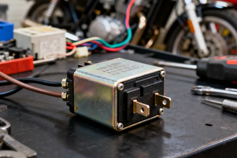
To measure relay contact resistance correctly, use a four-wire Kelvin voltage-drop method whenever lead and fixture resistance are significant compared with the result. Close the intended contact under the specified coil condition, force the exact test current stated in the relay data sheet or approved test plan, sense voltage directly at the defined terminals, and calculate R = V / I. Compare the result only with a limit obtained under equivalent conditions.
The short answer:
1. Define whether you are testing the relay alone, the relay plus socket, or a complete installed path.
2. Use separate force and sense connections at the specified terminals.
3. Use the model-specific test current, source-voltage limit, coil state, timing, and temperature.
4. Record actual current and sensed voltage, then calculate R = V / I.
5. Judge the result against the exact data-sheet or agreed production condition-not a universal milliohm number.
A normal two-wire multimeter can confirm gross continuity, but it normally cannot prove a low-milliohm acceptance limit. Its leads, clips, socket interfaces, probe pressure, thermal voltage, contact bounce, and an unsuitable test current can dominate the display. A useful result is therefore more than "23 mΩ." It is a traceable record of the relay, pole, closed contact, force/sense points, coil condition, current, voltage, timing, ambient, instrument, fixture, and acceptance rule.
Electrical safety boundary: Perform a low-resistance test only on an electrically isolated test setup. Disconnect external loads and supplies, prevent unintended backfeed, discharge stored energy, and verify the safe state before connecting a meter or current source. Never place an ordinary low-ohm instrument across a live mains or unknown energized circuit. High-energy and in-circuit tests require a qualified person, suitable protective equipment, and an approved procedure.
Choose the Measurement Before Choosing the Instrument
|
Test Question |
Recommended Scope |
Correct Comparison |
|---|---|---|
|
Does a new relay meet its initial contact-resistance specification? |
Four-wire test at the defined relay terminals, current, voltage condition, coil state, and timing. |
The exact model's initial limit under the same published method. |
|
Is a plug-in assembly creating excessive voltage drop? |
Sense at the socket terminals, then separate relay-only and socket/interface measurements. |
An assembly limit or known-good assembly baseline, not a relay-pin-only value. |
|
Will a contact carry a dry or micro-level signal? |
A controlled low-energy method performed before any test that can disrupt surface film. |
The relay's stated dry-circuit/minimum-load capability and an application-specific test plan. |
|
Why is an installed circuit losing voltage? |
A safe segmented voltage-drop investigation across relay, socket, terminals, and wiring. |
A same-path installed baseline and the system's functional/thermal requirements. |
|
Has switching duty changed the contact path? |
Repeat the same controlled method at defined endurance intervals, plus functional tests. |
A pre-test baseline and agreed post-life criteria; resistance alone does not prove life. |
This first decision prevents the most common category error: measuring one path and judging it with a limit written for another. Four-wire sensing removes most external force-lead error, but it cannot remove any terminal, socket, spring, busbar, or conductor that lies between the sense points.
1. What Relay Contact Resistance Actually Includes
Closed-contact resistance is not only the microscopic interface where two contact surfaces touch. It can include the movable spring, fixed contact support, terminals, welds, rivets, and other conducting parts between the measurement points. OMRON describes contact resistance as a combination of conductor resistance, boundary resistance at the contact interface, and constriction resistance where current is concentrated through small real contact areas. Panasonic likewise defines the catalog value as the combined resistance of the touching contacts, terminals, and contact spring.

The measured path can include more than the visible contact interface, depending on where the sense leads connect. Image: Relay Parts by David Boettcher, released into the public domain via Wikimedia Commons.
The measurement scope should match the decision:
- Relay-only incoming inspection: sense directly at the defined relay terminals so an external socket does not decide whether the component passes.
- Relay-and-socket qualification: include both pin/socket interfaces intentionally and write a separate assembly limit.
- Panel troubleshooting: move the sense points step by step to isolate the relay, socket, terminal blocks, connectors, and wiring.
- Endurance development: preserve the same sense geometry at every interval so the trend represents change rather than fixture revision.
The OMRON relay technical guide also states that catalog contact-resistance figures are initial specified values and that the number alone does not describe performance in actual operation. This is why a new-component specification, a minimum-load reliability claim, and a field voltage-drop reading must not be treated as interchangeable.
2. Why Four-Wire Kelvin Measurement Is the Milliohm Method
In a two-wire resistance measurement, the same two leads carry current and sense the resulting voltage. The display therefore includes the resistance of both leads, clips, probe-to-terminal interfaces, and any fixture path. If each lead and connection contributes only a few tens of milliohms, a healthy relay can appear to fail a low limit.
A four-wire, or Kelvin, connection separates the two functions:
- The force-high and force-low leads carry the controlled test current through the closed contact path.
- The sense-high and sense-low leads draw negligible current and read voltage close to the defined device terminals.
- The instrument calculates resistance from sensed voltage divided by forced current, or the operator records both values and performs the calculation.

Four-terminal sensing separates current forcing from voltage sensing. For a relay, place the voltage-sense connections at the exact terminals defined by the test plan. Diagram: FourpointContact Wiki by Georg Wiora, licensed under CC BY-SA 3.0 via Wikimedia Commons.
Four wires do not make every result automatically correct. A sense clip placed on the far side of a socket includes the socket. A sense point placed on an oxidized fixture surface can add instability. Reversing force and sense positions can introduce an unintended lead segment. The physical connection drawing belongs in the test specification, especially when suppliers and customers perform the same acceptance test at different sites.
Keysight's four-wire resistance guidance explains why remote sensing is required when residual lead resistance is comparable to the device under test. For production release, use a Kelvin-capable DMM, micro-ohmmeter, or a controlled source plus separate millivolt measurement with sufficient range, resolution, stability, and calibration.
3. Calculate Contact Resistance from Voltage Drop
The electrical calculation is Ohm's law:
R = V / I
Here, V is the voltage sensed across the defined closed path and I is the actual current through that path at the same time. Record actual current rather than assuming the source setting is exact.
Illustrative calculation: If the actual test current is 1.000 A and the sensed voltage is 18.0 mV, the apparent resistance is 18.0 mΩ. If the current is 100 mA and the sensed voltage is still 18.0 mV, the result is 180 mΩ. The convenient "millivolts equal milliohms" shortcut works only when current is exactly 1 A.
The Panasonic relay terminology guide shows a voltage-drop method and publishes illustrative test-current bands. It also notes that relays rated at 1 A or more are generally measured at 6 VDC and 1 A. This is a useful manufacturer example, not a universal test setting. A signal relay, reed relay, automotive relay, contactor, latching relay, or customer-qualified version may specify another condition.
When measuring very small voltage drops, thermal electromotive force can be comparable to the signal. Dissimilar metals and temperature gradients at clips, relay terminals, or a warming coil can produce microvolts. The Keysight low-resistance application note recommends controlling source settling, self-heating, offsets, noise, and thermal EMF. Current reversal or offset-compensated measurement can reduce DC offset, but use it only when it is compatible with the relay and the approved method. OMRON, for example, describes averaging forward- and reverse-polarity readings for DC relay contact resistance in its general guide.
4. Select Test Current and Open-Circuit Voltage from the Exact Specification
There is no universal contact-resistance test current. The current must be high enough to create a measurable voltage above noise and instrument resolution, yet low enough to avoid unwanted heating, contact-film disruption, or damage. Source voltage or compliance also matters because a high available voltage may puncture a film before the current settles.
Use this priority order:
- Exact model data sheet and manufacturer test drawing. Match the part number, contact form, contact material, coil version, terminal style, and revision.
- Customer-approved control plan or qualification specification. It should state current, voltage/compliance, switching sequence, timing, sense points, and limit.
- Applicable standard named by the drawing or contract. Confirm the edition and any supplementary requirements.
- Supplier engineering agreement. If the data sheet gives a resistance value without a complete method, resolve the gap before creating a pass/fail gate.
A model-specific example shows why copying a generic setting is risky: the OMRON G6K data sheet specifies a 100 mA voltage-drop method for its contact-resistance figure, while broader manufacturer terminology pages often show 1 A for higher-current relay categories. Neither value should be transferred automatically to a different relay.
Also control dwell. Test power is P = V × I, and heat changes conductor resistance and may change contact conditions. A long high-current dwell can make the displayed resistance drift upward. If the expected sensed voltage is too small for reliable measurement, improve the instrument, fixture, shielding, range, or method rather than simply increasing current beyond the approved condition.
5. Dry-Circuit Testing Is a Different Question
A dry-circuit test asks whether a contact can conduct a low-energy signal without the test itself breaking through oxide or contamination film. It is not merely a normal contact-resistance test on a lower range. If a higher voltage or current cleans, softens, or punctures the surface film, the relay may appear excellent immediately afterward while still being unsuitable for the original micro-load application.
The Keithley Low Level Measurements Handbook describes a typical dry-circuit approach that limits open-circuit voltage to 20 mV or less and current to no more than 100 mA to avoid oxide-film puncture. Those values explain the measurement principle; they are not a universal relay qualification rule. The exact relay rating, customer requirement, instrument compliance behavior, test order, and application signal control the final plan.
TE Connectivity's relay failure-diagnosis guide warns not to use a dry-circuit contact-resistance method unless the relay is rated for dry-circuit operation. It also separates new-relay contact-resistance testing from functional checks on relays that have already switched loads.
Test-sequence rule: When low-level contact behavior is the question, perform the approved dry-circuit test before any high-current resistance, continuity, burnishing, cycling, or load test that could change the surface. Record the original result before investigative conditioning.
A dry contact in control-system language also means that the relay contact does not supply its own voltage. That wiring term does not automatically mean the relay is qualified for dry-circuit measurement or reliable micro-load switching. The electrical energy and contact capability still need to be specified.
6. Build a Repeatable Bench Setup
|
Setup Control |
Good Practice |
Risk If Uncontrolled |
|---|---|---|
|
Instrument and range |
Use four-terminal capability, sufficient low-voltage resolution, controlled current, valid calibration, and a suitable reference standard. |
Noise, offset, range error, or inadequate resolution appears as part variation. |
|
Force/sense geometry |
Place independent sense points immediately inside the force points at the defined relay terminals. |
Lead, socket, terminal, or fixture drop is unintentionally included. |
|
Fixture pressure |
Use repeatable probes or a dedicated fixture without bending, scraping, heating, or stressing terminals. |
Freehand clip movement and variable surface contact create false scatter or damage. |
|
Coil source and state |
Apply the approved stable coil condition and verify voltage at the coil terminals under load. |
Partial pickup, chatter, heating, or the wrong contact state makes readings unstable. |
|
Timing and temperature |
Define settle time, measurement window, ambient range, relay conditioning, and dwell. |
Bounce, thermal EMF, self-heating, and coil warm-up change the result. |
|
Data capture |
Save raw V and I, calculated R, pole/contact, part/lot, fixture and instrument IDs, and deviations. |
A later investigation cannot distinguish product variation from a changed test system. |
For a one-time engineering check, a Kelvin DMM or micro-ohmmeter with suitable clips may be enough. For incoming inspection, PPAP/FAI, or supplier lot release, use a dedicated fixture whose force and sense locations are documented. Qualify the measurement system with a low-resistance reference and a repeatability/reproducibility study before the measurement becomes a commercial rejection criterion.
Do not mechanically disturb a sealed or returned relay merely to obtain a cleaner number. Cutting the case, bending terminals, polishing contacts, soldering onto the sample, or repeatedly cycling it may destroy evidence needed for failure analysis. If destructive examination is required, retain an untouched comparison sample and document each step.
7. Step-by-Step Four-Wire Relay Contact Resistance Test
- Define the purpose. State whether this is new-relay conformance, relay-plus-socket validation, dry-circuit evaluation, endurance trending, or field fault isolation.
- Identify the exact specimen. Record manufacturer, complete part number, revision, coil voltage/type, contact form, pole, terminal style, lot, and whether the contact is unused or has switched a load.
- Obtain the governing method. Record the specified current, available/open-circuit voltage, coil state, switching sequence, preconditioning, settle time, temperature, sense terminals, and limit.
- Make the circuit safe. Isolate all external sources and loads, discharge stored energy, and verify that no backfeed path remains.
- Check the measurement system. Warm up and zero the instrument as required, inspect the fixture, verify the selected range, and check an appropriate low-resistance reference.
- Connect the force pair. Route controlled current through the complete intended closed-contact path using conductors rated for the test.
- Connect the sense pair. Place sense-high and sense-low at the exact defined terminals, inside the force connections, with stable independent contact.
- Set the electrical conditions. Program the approved current and compliance/source-voltage limit. Confirm actual current and avoid a dwell that causes unwanted heating.
- Close the correct contact. For a normally open contact, this usually means energizing the coil at the defined voltage. For a normally closed contact, it usually means the released condition. Follow the exact test sequence for latching, polarized, or special relays.
- Wait for the defined measurement window. Do not sample during operate time, contact bounce, release, or coil chatter. Keep the timing consistent across samples.
- Read voltage and current together. Calculate R = V / I, or confirm that the instrument's four-wire display uses the same measurement scope and settings.
- Repeat according to plan. Measure every specified pole and NO/NC path. If polarity reversal or multiple operations are required, preserve their order and store individual readings-not only the average.
- Judge like against like. Apply the exact criterion, uncertainty/guard-band rule, and outlier procedure. Never improve a failing sample before recording its first condition.
- Document disposition. Save the raw values, calculated result, operator/time, ambient, instrument/fixture IDs, deviations, and reason for any retest.
For multi-pole relays, one good pole does not qualify the others. Measure each required contact path because spring alignment, contact force, contamination, terminal geometry, and local heating can vary. For changeover contacts, define separate NO and NC paths and the coil state used for each. For latching relays, state set/reset history rather than assuming a power-off state tells the reader which contact is closed.
When the test is part of supplier qualification, a control plan should lock the fixture drawing, firmware/settings, settle time, arithmetic, rounding, and data format. Otherwise, two laboratories can both claim to use "four-wire 1 A" and still measure different physical paths at different times.
8. Common Measurement Errors and Their Signatures
|
Observed Result |
Likely Causes |
How to Separate Them |
|---|---|---|
|
All relays read high |
Two-wire method, sense points outside the target path, wrong current, fixture oxidation, or a changed socket. |
Verify a reference, inspect connection geometry, compare relay-only and assembly paths, and record actual V/I. |
|
Readings vary every operation |
Contact bounce, coil chatter, moving clips, variable probe pressure, intermittent socket, or inadequate settle time. |
Log V, I, and coil voltage versus time; use a fixed fixture; separate operation-to-operation and measurement-system variation. |
|
Resistance rises during the reading |
Self-heating, long dwell, coil warm-up, thermal EMF drift, or an unstable current source. |
Trend voltage, current, and temperature; shorten dwell only within the approved method; test a reference under the same timing. |
|
High-current test passes, micro-signal fails |
The stronger test disrupted contact film or does not represent the minimum-load application. |
Review contact material/rating and run the approved low-energy test first on an undisturbed sample. |
|
Only one pole is high |
Local contamination, wear, alignment/contact-force variation, terminal damage, or one fixture channel. |
Swap fixture channels without changing the sample state, repeat defined operations, and retain the part for structured analysis. |
|
Field path is high but relay-only is normal |
Socket, terminal block, crimp, connector, wiring, or localized heat damage. |
Move Kelvin sense points segment by segment using a safe isolated test plan. |

Contact condition, force, films, contamination, and switching history can change conduction at the real contact spots. Image: Relay Contacts by Pineywoodsdavid, licensed under CC BY-SA 3.0 via Wikimedia Commons.
A high reading does not identify the failure mechanism by itself. Contact erosion, material transfer, arcing residue, corrosion, contamination, a weak mechanical closure, insufficient coil drive, and external connection resistance can produce similar numbers. Inspect the electrical path first, then combine the resistance result with contact-state timing, coil voltage, load waveform, operating history, environmental evidence, and-when justified-non-destructive or destructive analysis.
Equally, a low resistance reading does not prove that the relay can switch the intended load. It says nothing by itself about inrush, breaking DC current, electrical life, welding risk, insulation, dielectric strength, surge, vibration, temperature rise, or fault behavior. Review the complete load duty and the exact relay ratings.
9. Set a Defensible Acceptance Criterion
There is no universal "good relay contact resistance." The acceptable value must be attached to a test method and a purpose. A 50 mΩ initial maximum from one model cannot qualify another model, and it cannot automatically become a field replacement threshold after years of switching.
|
Use Case |
Defensible Criterion |
Evidence to Keep |
|---|---|---|
|
Incoming inspection |
Exact model's initial limit reproduced at the published current, voltage, coil state, sense points, and sample condition. |
Data sheet revision, sampling plan, raw V/I/R, fixture drawing, calibration, and lot identity. |
|
Supplier PPAP/FAI |
Customer-supplier protocol with method capability, guard-band/disposition rules, and change control. |
Gauge study, sample status, individual-pole data, outliers, deviations, and retained samples. |
|
Endurance development |
Change from a same-method baseline at defined intervals, paired with load-switching and functional criteria. |
Load waveform, suppression, cycle count/rate, temperature, failures, and interval data. |
|
Installed maintenance |
Safe same-path voltage-drop baseline and system-specific thermal/functional limits. |
Sense locations, load/temperature, isolation procedure, segmented readings, and operating history. |
|
Dry/micro-load application |
Approved low-energy method tied to the real signal, contact technology, environment, and reliability objective. |
Open-circuit limit, test current, sequence, undisturbed samples, contact rating, and application data. |
Before using milliohm data to accept or reject supplier lots, quantify the measurement system. Check resolution, accuracy, calibration uncertainty, reference stability, fixture repeatability, operator effect, contact operation sequence, coil supply, sample temperature, timing, and software rounding. If gauge variation consumes a large share of the tolerance, tightening the relay limit creates false rejects and false accepts rather than better quality.
IEC 61810-7:2006 lays down general test and measurement procedures for electromechanical elementary relays and notes that specific designs or applications may require supplementary requirements. The IEC publication record is useful for defining the standards framework, but the purchased standard, exact relay documentation, customer drawing, and applicable equipment standards control a formal compliance program.
10. Use the Result for Supplier Qualification and Relay Selection
A strong relay RFQ should request more than a bare contact-resistance number. Ask the supplier to identify:
- the exact relay configuration, contact form, contact material, terminal style, coil version, enclosure, socket if applicable, and drawing revision;
- whether the published resistance is maximum or typical, initial or post-life, and relay-only or assembly-level;
- the force/sense terminal definition, measurement current, voltage/compliance, coil condition, switching sequence, settle time, ambient, and preconditioning;
- the intended application voltage/current, load type, inrush, switching frequency, expected life, environment, and minimum-load requirement;
- production fixture, instrument range, calibration, MSA/gauge capability, sampling plan, raw-data format, and outlier disposition;
- change notification for contact material/plating, geometry, terminal, process, production site, fixture, current, firmware, or acceptance limit.
QIANJI buyers can start with the complete relay product range, then review general-purpose relays or power relays according to contact arrangement and load duty. Product selection still requires the exact data sheet and application conditions; a category page is not a substitute for engineering approval.
Need a repeatable supplier test plan?
Send QIANJI the complete relay part number or target configuration, load voltage/current and type, coil condition, contact-resistance requirement, proposed current/voltage circuit, sense-point drawing, sample quantity, and whether the objective is incoming inspection, dry-signal reliability, endurance, or field diagnosis. Submit the application and test requirements here.
Frequently Asked Questions
What is a good relay contact resistance?
There is no universal good value. A result is acceptable when it meets the exact model's stated limit under the same current, voltage condition, contact path, coil state, timing, temperature, and sample condition-or when it remains within a validated application baseline. Do not compare a relay-plus-socket reading with a relay-only initial limit.
Can I measure relay contact resistance with a normal multimeter?
A two-wire DMM can screen for open circuit or grossly high resistance, but lead and probe resistance may overwhelm a milliohm result. Use a four-wire Kelvin-capable instrument or a controlled current source with separate voltage sensing for acceptance or detailed diagnosis. The instrument's test current and available voltage must still match the relay method.
Why does a four-wire test read lower than a two-wire test?
The two-wire result includes voltage drop in both leads and their contact interfaces. Kelvin sensing measures voltage with a separate high-impedance pair at the defined terminals, so most force-lead drop is excluded. If the difference remains large or unstable, verify sense placement, fixture condition, and the path included by each method.
What test current should I use?
Use the current specified in the exact relay data sheet or approved test plan. Manufacturers publish different conditions for different relay families; 100 mA and 1 A are both seen in real documentation. Increasing current can improve signal level but may cause heating or alter contact film, so the largest available current is not automatically correct.
How do I measure a normally open relay contact?
Connect the defined four-wire path while the NO contact is open, then operate the coil according to the approved sequence so the contact closes under the required electrical condition. Measure after the defined settle time, not during pickup or bounce. Use the specified nominal/approved coil voltage and verify it at the relay terminals.
How do I measure a normally closed relay contact?
The NC path is normally measured in its closed released state, unless the model-specific procedure requires another sequence. Confirm the relay state, especially for latching or polarized types. For a changeover relay, label the common-to-NC and common-to-NO results separately and use the correct coil state for each.
Is dry-circuit contact resistance the same as normal contact resistance?
No. Dry-circuit testing limits energy so the measurement does not disrupt surface film. A normal initial contact-resistance specification may use a higher voltage/current condition. A relay can pass a stronger test and still be unreliable for a micro-level signal, so dry-circuit capability and test sequence must be specified explicitly.
Why does relay contact resistance change after cycling or load switching?
Possible contributors include contact wear, material transfer, arcing residue, films, contamination, heat, bounce, insufficient coil drive, or a changed socket/fixture. Repeat the original method, segment external resistance, and review the actual load waveform and environment. The resistance number alone cannot identify the root cause.
Does low contact resistance prove the relay is suitable for my load?
No. It verifies closed-path conduction under one condition. It does not prove make/break capacity, inrush tolerance, DC interruption, electrical life, insulation, dielectric performance, temperature rise, vibration behavior, or system safety. Relay selection and validation must cover the complete load, environment, switching frequency, protection, and required life.
Final Measurement Checklist
- Define the decision and the physical path before testing.
- Use the exact model's current, voltage/compliance, coil state, sequence, and limit.
- Use four-wire Kelvin sensing for milliohm acceptance work.
- Place sense leads at the intended terminals and keep the fixture mechanically repeatable.
- Control bounce, chatter, settle time, temperature, dwell, offset, and thermal EMF.
- Perform any dry-circuit test before higher-energy conditioning and only on a suitable relay.
- Record raw voltage and current, not only a rounded pass/fail result.
- Compare new, used, relay-only, assembly, and field measurements only within their proper scopes.
- Use contact resistance as one piece of evidence, not as proof of load suitability or service life.
Correct relay contact resistance measurement is a controlled experiment, not a quick probe reading. When the path, electrical conditions, mechanical state, timing, measurement system, and acceptance criterion are all defined, the result becomes useful to design engineers, quality teams, suppliers, buyers, and maintenance personnel.
Technical References
- OMRON - Further Information of General Purpose Relays: contact-resistance composition, four-terminal voltage-drop method, test-current examples, initial-value boundary, bounce, film, and thermal EMF.
- Panasonic Industry - Relay Terminology: voltage-drop method, contact-path definition, and manufacturer test-current examples.
- Keysight - Precise Low Resistance Measurements: Kelvin connections, measurement current, self-heating, source settling, offset, noise, and thermal EMF.
- Keithley - Low Level Measurements Handbook: low-resistance and dry-circuit measurement principles.
- TE Connectivity - Verification and Diagnosis of Suspected Relay Failures: new-versus-used relay boundaries, contact state, specified test conditions, dry-circuit cautions, and voltage-drop calculation.
- IEC 61810-7:2006 publication record: general electromechanical elementary-relay test and measurement procedures.