


Protect relay contacts from inductive loads by controlling the stored magnetic energy when the contacts open-and by selecting a relay whose published switching duty matches the real load. A reverse diode is a common starting point for many DC coils when slower release is acceptable. A diode-plus-Zener or TVS can permit faster DC release at a higher controlled voltage. RC snubbers and MOVs are common candidates for appropriate AC circuits. None is universal: the load, AC/DC voltage, release time, contact rating, wiring, switching rate and measured transient determine the correct solution.
The most important distinction
A suppressor across the relay's own coil protects the PLC output or coil driver and changes that relay's release behavior. A suppressor across the external solenoid, contactor coil, motor or transformer switched by the contacts reduces the contact-side turn-off transient. These are two independent circuits. One suppressor does not automatically protect both.
- Use the exact inductive, motor, lamp, transformer or DC contact rating-not a resistive headline rating.
- Choose the suppression family from load voltage type, stored energy, release-time need and permitted clamp voltage.
- Place the suppressor close to the inductive load when the manufacturer-approved circuit allows it.
- Check both contact break and the next make; some capacitor arrangements reduce opening arcs but increase closing current.
- Validate the completed circuit with real voltage/current waveforms, mechanical release time, temperature and repetitive duty.
Safety boundary: this article explains engineering selection and validation; it is not a live-wiring procedure, universal component-value prescription or safety-system approval. Inductive circuits can create hazardous transient voltages, and a welded contact can leave a load energized after the command is OFF. Use qualified personnel, approved isolation procedures, correctly rated test equipment, the exact device manuals and applicable standards. A PLC bit, indicator LED or clicking sound is not proof that the power path is de-energized.
1. Why Inductive Loads Damage Relay Contacts
Solenoids, relay coils, contactor coils, motors and transformers store energy in a magnetic field while current flows. When a relay contact opens, the current cannot fall to zero instantly. The inductive element therefore changes its terminal voltage in an attempt to keep current flowing. This behavior is commonly expressed as e = −L(di/dt).
If the circuit provides no controlled current path, voltage can rise until current continues through an arc across the separating contacts, insulation leakage or another unintended route. The arc heats the contact surface, transfers and removes material, generates electromagnetic interference and can contribute to sticking or welding. TE Connectivity's relay-contact guidance emphasizes that contact life is application-dependent and that appropriate arc suppression can reduce destructive arcing.
Stored magnetic energy: E = ½LI2
Useful for understanding why current matters, but not sufficient to select a suppressor or approve a relay.
The energy relationship shows that, with inductance unchanged, doubling current increases stored energy by four times. Real loads are more complicated: winding resistance, armature motion, saturation, cable impedance, contact bounce, parasitic capacitance and driver behavior all influence the transient. A 0.5 A solenoid can therefore be a more difficult break duty than a higher-current resistive heater.
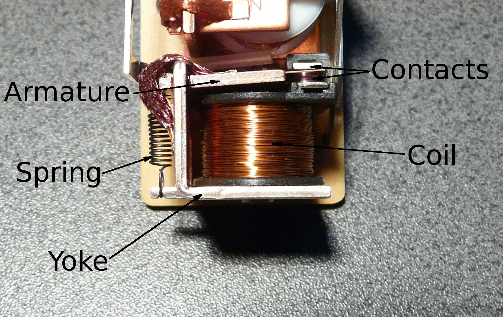
The relay coil, armature and switching contacts perform different functions; suppression can affect either the coil circuit or the contact-side load circuit. Photo and labels by David Boettcher, via Wikimedia Commons, released to the public domain. This is a general relay illustration, not a QIANJI product drawing.

| Event | What happens electrically | Contact consequence |
|---|---|---|
| Load energized | Current builds and magnetic energy is stored | Contacts carry current; terminal and contact heating still matter |
| Contact starts opening | The load opposes the rapid current decrease | Voltage rises across the small opening gap |
| Uncontrolled interruption | Current may continue through an ionized arc | Erosion, material transfer, noise and welding risk increase |
| Controlled interruption | A correctly selected path or clamp absorbs/dissipates energy | Arc stress can fall, but release time and other trade-offs change |
2. Find the Exact Circuit That Needs Protection
In a typical machine, "the relay circuit" may actually contain two or more inductive circuits. A PLC transistor may drive an interface-relay coil. The interface relay's contacts may then switch an AC contactor coil or a DC valve solenoid. Each inductive element has its own stored energy, interrupting device, current return path and timing requirement.
Draw the circuit at turn-off. Mark every contact or semiconductor that interrupts current, identify the inductive element connected to it and trace where current can flow after the switch opens. Do not stop at the control label. The useful question is: which opening switch sees energy from which inductor?
| Circuit boundary | Primary risk | Protection objective |
|---|---|---|
| PLC transistor → relay coil | Driver overvoltage, noise and altered relay release | Protect the output while preserving required contact motion and timing |
| Relay contact → DC solenoid | Contact arc, erosion, noise and delayed valve release | Control the load transient without unacceptable process delay |
| Relay contact → AC contactor coil | Inductive break arc, interference and release behavior | Use an AC-compatible suppression method and verify drop-out |
| Contactor → motor or transformer | High make current, break arc and system EMC | Use the correct switching category and a complete load strategy |
A diode across a valve solenoid can reduce stress on the contacts that switch that valve. It does not protect a PLC transistor driving a separate interface-relay coil. Similarly, a diode across the interface-relay coil can protect the PLC output, but it does not suppress the AC contactor coil switched by the relay contacts. Both circuits may need protection, but they require separate decisions.
3. Select the Relay Before You Select the Suppressor
Suppression improves an appropriate switching circuit. It cannot convert an undersized contact into a motor starter, make an AC rating valid for DC, or turn a carry-current figure into a permitted break-current figure. Begin with the real duty: supply type, voltage tolerance, steady current, inrush, inductive break behavior, switching frequency, required electrical life, ambient temperature, cable length and fault protection.
Use the exact product's published load category and life conditions. A "10 A" marking is incomplete without voltage, AC/DC, load type and test conditions. Do not combine separate maximum voltage, maximum current and maximum switching-power figures into an operating point unless the manufacturer explicitly permits that combination.
| Data to verify | Why it matters | Common mistake |
|---|---|---|
| Rated load and category | Shows whether the test resembles a solenoid, motor, transformer or DC load | Applying a resistive rating to inductive breaking |
| Make and break limits | Separates inrush stress from interruption stress | Using normal current as the only selection number |
| Electrical-life condition | Connects expected operations to voltage, current, load and rate | Treating mechanical life as loaded contact life |
| Coil and release data | Suppression can change the motion that opens the contacts | Reviewing only the load side and ignoring coil drive |
| Temperature and installation | Heat, terminal resistance and socket/PCB limits consume margin | Using room-temperature bench data as production proof |
| Fuse/breaker conditions | Short-circuit protection is a separate system function | Expecting a snubber to clear a fault |
QIANJI's general-purpose relays, power relays and PCB relays provide different mechanical, mounting and load options. Category pages are a starting point; final approval requires the exact model's data and real switching duty.
4. Diode, TVS, RC Snubber and MOV Compared
There is no single best suppressor. Omron's official relay guidance describes a diode as generally effective for DC loads and a varistor or CR network as common for AC loads, while repeatedly directing designers to test the actual equipment. The table below is a decision aid, not a universal wiring diagram.
| Method | Good starting use | Main trade-off to verify |
|---|---|---|
| Reverse diode | Many DC coils or solenoids when longer release is acceptable | Slow current decay, polarity, pulse current and repetitive heating |
| Diode + Zener/TVS | DC loads needing faster release than a simple diode provides | Higher clamp voltage at contacts, driver, cable and suppressor |
| RC snubber | Many AC inductive loads and selected documented DC topologies | Off-state leakage, capacitor make current, pulse power and safety rating |
| MOV/varistor | Appropriately rated AC loads and some defined DC cases | Continuous voltage, clamp level, energy, repetition, degradation and end-of-life |
| Vendor module | Documented relay socket, contactor or controller accessory | Exact load compatibility, installed location and release time |
| Different switch | High-cycle, high-energy, special DC or severe inrush duty | Thermal design, leakage, EMC, fault behavior and safe state |
If the required duty exceeds general electromechanical relay data, changing the architecture may be the correct answer. A suitable contactor, motor starter, DC contactor, protected semiconductor driver or solid-state relay can move the duty to a technology designed for it. The alternative still needs its own thermal, leakage, EMC and fault analysis.
5. Flyback Diode for a DC Inductive Load
A reverse-biased diode across a DC load does not normally conduct while the load is energized. When the contact opens, the inductive voltage reverses and forward-biases the diode. Current then recirculates through the load and diode instead of maintaining a large voltage across the opening contact.

A flyback diode gives current from a DC inductive load a local recirculation path after the switch opens. Diagram by Inductiveload, via Wikimedia Commons, released into the public domain. This conceptual image is not a model-specific QIANJI wiring instruction.

The low clamp voltage is effective at limiting contact-side voltage, but it makes current decay slowly. TE notes that diode suppression can lengthen the hold-up time of an inductive load. A slow release may be harmless for an auxiliary relay but unacceptable for a valve, clutch, brake, contactor, sequencing function or safe-state transition.
Verify diode polarity, reverse voltage during normal energization, forward current during decay, pulse duration, repetitive duty, temperature and failure effect. If the load or relay module already contains a diode, LED or suppression network, review its internal schematic before adding another component. A simple flyback diode must not be placed across an AC load as though the supply were DC.
6. Diode Plus Zener or TVS for Faster DC Release
A diode-plus-Zener or transient-voltage-suppressor arrangement permits the voltage to rise to a controlled level before the suppressor conducts strongly. The higher voltage drives a faster decrease in current, so the solenoid or contactor can release sooner than it would with a simple diode. Omron identifies this as an option when a diode circuit's release time is too long.
The trade-off is deliberate: faster demagnetization increases voltage stress. Check the maximum permitted voltage at the relay contact, PLC output or transistor, cable insulation, load terminals, suppressor and any shared circuit node. Select the TVS or Zener from its working/standoff voltage, clamping voltage at the relevant current, dynamic behavior, pulse energy, repetition, temperature and tolerance-not from nominal coil voltage alone.
Useful design rule
Lower clamp voltage generally means less voltage stress but slower current decay. Higher controlled clamp voltage generally means faster release but more electrical stress. The approved point is where both the voltage limits and the functional release requirement are satisfied with margin.
7. RC Snubber: Check Break and the Next Make
An RC snubber uses a capacitor and resistor in series. At contact opening, the capacitor accepts transient current and limits the immediate voltage rise; the resistor limits current and dissipates energy. It can be useful for AC inductive loads and selected documented DC applications, and it can reduce arcing and EMI.
The capacitor remains part of the circuit at the next closing event. A poor topology or value can store energy or draw charging current through the contacts and create a make-current spike. Both Omron and TE warn that capacitor arrangements which look effective at break can contribute to contact welding at make if current is not controlled. This is why the resistor is not an optional decoration.
Before approval, define the exact connection point, AC or DC voltage, frequency, peak transient, allowable leakage, resistor pulse and average power, capacitor voltage and safety class, tolerance, temperature, switching rate and release-time effect. A familiar value copied from another machine may be ineffective, overheat, keep a sensitive coil partially energized or stress the contacts on closure.
8. MOV: Convenient Clamp, Finite Stress Capacity
A metal-oxide varistor is a bidirectional nonlinear clamp. It remains relatively high impedance below its clamp region and conducts more heavily as voltage rises. For an appropriately rated AC inductive load-and some defined DC uses-it can limit the voltage across the load or contact circuit without the polarity restriction of a simple diode.
Select it from maximum continuous voltage, tolerance, clamping voltage at actual current, surge energy, pulse shape, switching rate, temperature, leakage and documented end-of-life behavior. Repeated energy absorption can change MOV characteristics. A clamp chosen too high may offer little contact protection; one too close to normal line voltage may leak, heat or age prematurely. Review the component supplier's protective and thermal requirements, especially for mains-connected circuits.
RC and MOV approaches can both be valid for AC coils, but they are not interchangeable labels. One shapes voltage and current through a resistor-capacitor network; the other clamps above a nonlinear voltage threshold. Compare their measured release behavior, leakage, transient reduction, repetitive energy and failure consequences in the actual circuit.
9. Put the Suppressor at the Right Physical Location
As a general control-system practice, place the suppression device as close as practical to the inductive load it protects, unless the relay, controller or load manufacturer specifies another arrangement. Rockwell Automation's current Micro800 controller manual recommends a suppression device directly across the inductive device and as close as possible to the load. A local path keeps the transient loop small and can reduce voltage and noise on the cable.

A field solenoid is both an electrical inductive load and a mechanical device with a required release time. Photo by PetrS., via Wikimedia Commons, licensed under CC BY-SA 3.0. This is a general application image, not a QIANJI installation.

A suppressor mounted only at a panel output may protect that output, yet a long cable and remote coil can still produce a large transient loop and radiated noise. Conversely, a load-mounted device may face moisture, vibration, temperature, enclosure and serviceability constraints. Cable resistance, inductance and capacitance are part of the circuit, so a short-lead bench test may not represent the installed machine.
| Placement | Potential benefit | Question to prove |
|---|---|---|
| Across the DC load | Local recirculation or clamp path | Does the load release fast enough under all conditions? |
| Across the AC load | Limits the transient near its source | Are continuous voltage, leakage and energy ratings suitable? |
| Across the contacts | Can control contact-gap voltage in documented circuits | What current flows while open and at the next make? |
| At controller output only | Compact protection for output electronics | Is the transient controlled at the physical load and cable? |
| Integrated module/socket | Known mounting and documented compatibility | Does it protect the intended coil or the separate switched load? |
10. AC and DC Switching Need Different Assumptions
AC current crosses zero every half cycle, which can help an arc extinguish. DC has no natural current zero, so contact gap, circuit impedance and the suppression arrangement must force the arc to end. This is one reason a contact may have very different AC and DC ratings even at apparently similar current.
Do not transfer an AC rating to DC or assume that a diode used on DC is suitable for AC. For AC coils, a properly rated RC network, MOV or manufacturer accessory is a more typical starting family. For DC coils, polarity, release delay and clamp voltage become prominent. In both cases, verify inrush, actual break waveform, switching frequency and electrical-life conditions.
Specialized phase-controlled switching can improve some AC contact duties, but it is not a generic substitute for suppression. Iron-core loads such as transformers may draw severe inrush if switched at an unfavorable phase. Timing approaches require measurement of the actual load and control that accounts for relay operate/release variation and bounce.
11. Why Coil Suppression Can Change Contact Life
When suppression is installed across the relay's own DC coil, it protects the device that turns that coil off. It also changes how quickly the magnetic field collapses. A simple diode can retard armature return, delay contact opening and reduce contact separation speed.
TE Connectivity documents that this slower release can reduce the relay's ability to break light tack welds and, in some applications, contribute to intermittent sticking of normally open contacts. Omron likewise cautions that surge suppressors can increase release time and requires checking operation under actual load conditions. This does not mean a flyback diode is generally harmful. It means coil-side protection must be reviewed together with relay dynamics and the contact load.
Keep the two effects separate:
- Diode across an external DC solenoid: normally reduces the turn-off transient seen by the contacts, but may delay that solenoid's release.
- Diode across the switching relay's own coil: protects its driver, but may delay that relay's armature and change how its contacts open.
Where timing or life matters, measure coil current, contact voltage/current and the physical load response together. A controller command timestamp alone cannot reveal contact separation or valve release.
12. A Measurement-Led Validation Workflow
The correct protection circuit is the one that meets defined electrical, mechanical and system criteria in the completed assembly. Use probes, current sensors, grounding methods and isolation appropriate to the expected voltage and energy. Poor probing can create a hazard or hide the real transient.

Relay-contact protection should be verified with electrical waveforms and functional timing evidence. Generic test-equipment photo by Glrx, via Wikimedia Commons, licensed under CC BY-SA 4.0.

- Classify the load. Record AC/DC, voltage tolerance or frequency, normal current, expected inrush, coil resistance/inductance or L/R data, switching rate and required release time.
- Identify the exact switch and driver. Record relay part number, contact form, load ratings, life conditions, coil/input type, built-in suppression and temperature limits.
- Draw the opening-current path. Include the coil/load, opening contact, cable, commons, supply, existing clamp and any backfeed route.
- Define acceptance criteria. Set permitted transient voltage, functional release time, leakage, EMC behavior, temperature and expected operating life before choosing a part.
- Select a supported topology. Use the relay, controller and load manufacturer's circuit guidance; calculate ratings from the full voltage, current, energy, temperature and repetition conditions.
- Install at production-intent location. Include real cable length, terminals, grounding/reference scheme, enclosure and neighboring wiring.
- Measure make and break. Capture contact/load voltage, load current, clamp voltage, coil terminal voltage, release time and any PLC reset, input noise or communication upset.
- Test expected extremes. Include supply tolerance, hot/cold ambient, maximum load, worst cable, repeated duty, startup and approved interruption/fault scenarios.
- Freeze the evidence. Record the exact suppressor, orientation, location, approved alternatives, waveforms and acceptance results in the drawing, BOM and test report.
| Measure | What it reveals | False confidence to avoid |
|---|---|---|
| Current at make | Inrush or capacitor charging stress | A steady clamp-meter value represents closing current |
| Voltage/current at break | Actual transient, clamp action and contact duty | Normal supply voltage reveals counter EMF |
| Mechanical release time | Valve, clutch, contactor or relay response | Electrical decay and physical release are identical |
| Coil terminal voltage | Supply sag, wiring drop and turn-off dynamics | Power-supply output equals coil-terminal voltage |
| Temperature/repetition | Suppressor, contact, terminal and wiring stress | One cold bench cycle proves life |
| System/EMC response | PLC resets, false inputs or communication upset | No visible spark means no transient problem |
13. Four Practical Troubleshooting Scenarios
A 24 VDC valve releases too slowly after a diode is added
The diode may have reduced arcing exactly as intended while extending coil-current decay. Capture current decay, valve release time and contact voltage. If the release requirement cannot tolerate a simple diode, evaluate a manufacturer-supported higher-clamp strategy such as diode-plus-Zener/TVS, while confirming every connected voltage and energy limit.
A PLC transistor drives an interface relay that switches an AC contactor coil
Analyze two circuits. The relay coil needs a protection method compatible with the PLC output and the relay's release dynamics. Separately, the AC contactor coil needs an AC-compatible method that protects the interface-relay contacts and preserves contactor release. A diode on the interface-relay coil does not suppress the AC load.
A panel snubber does not stop noise from a remote solenoid
The long field cable is part of the transient loop. Compare waveforms at the panel and load. If product guidance permits, a suitable suppressor closer to the solenoid may shrink the loop. Environmental protection, service access, release time, cable voltage and fault protection remain part of the decision.
A relay still erodes contacts after an MOV is installed
Check whether the MOV actually clamps at a useful voltage and survives repetitive energy, but do not stop there. The relay may have the wrong load category, the contactor coil may chatter during supply dips, or inrush may damage contacts at make. Suppression cannot correct an unstable control supply or an unsuitable contact device.
14. What to Include in a Relay and Suppression RFQ
"24 V relay with 10 A contacts" is not enough information for an inductive-load selection. Give suppliers the same duty and ask for the same evidence so quotations are technically comparable.
| RFQ block | Information to provide | Evidence to request |
|---|---|---|
| Load | Solenoid, coil, motor, transformer, valve or mixed load; AC/DC voltage; current; inrush | Matching contact category, switching limits and life condition |
| Stored energy | Inductance, L/R, coil power/resistance, manufacturer curve or captured waveform | Supported suppression topology and rating assumptions |
| Timing/duty | Operations per hour, expected life, release target and sequence constraints | Release-time effect and repetitive-duty basis |
| Control circuit | PLC output type, relay coil, supply range, PWM/test pulse and built-in suppressor | Driver compatibility and coil-dynamics guidance |
| Installation | Cable length, load location, temperature, enclosure, terminals and grounding | Approved location, component limits and test plan |
| Protection | Fuse/breaker, prospective fault context and required coordination | Clear separation of transient suppression and fault protection |
Ask: "Which published contact rating and electrical-life condition match this exact AC/DC inductive duty? Which suppression topology and location do you recommend? What release-time change, clamp voltage, energy and temperature assumptions apply? What real-load test should we perform?" A defensible supplier response states conditions rather than only naming a component.
Discuss Your Inductive-Load Application with QIANJI
Send the exact relay/contact part number, load type, AC/DC voltage, steady and inrush current, inductance or L/R data, switching frequency, required release time, cable length, PLC output type, existing suppression and available waveform captures. QIANJI can help identify candidate relay categories and the model data needed for your application validation.
Frequently Asked Questions
Why does an inductive load arc relay contacts at turn-off?
The load's magnetic field tries to keep current flowing after the contact starts to open. Voltage rises until current finds a path. Without a suitable clamp or recirculation path, an arc can form across the opening contacts, causing erosion, material transfer, noise and possible sticking.
What is the best protection for a DC solenoid?
A reverse diode is a common starting point when slower release is acceptable. If release must be faster, a manufacturer-supported diode-plus-Zener/TVS or another higher-clamp solution may be appropriate. Select from the real coil energy, contact/driver voltage limits, pulse duty, temperature and timing-not nominal voltage alone.
Should the diode go across the relay coil or the switched load?
Put it across the DC inductive element whose transient must be controlled, unless product documentation specifies another topology. A diode across the relay coil protects its driver. A diode across an external solenoid protects the contacts switching that solenoid. If both circuits are inductive, analyze each one separately.
Can a flyback diode make a valve release too slowly?
Yes. The diode holds the clamp voltage low, so coil current and magnetic force decay more slowly. Measure physical valve release under supply, temperature and load extremes. If the delay is unacceptable, consider an approved higher-voltage clamp and recheck all electrical limits.
Can an RC snubber cause contact welding?
Yes, if its value or placement creates excessive capacitor charging or discharge current through the contacts when they close. Evaluate the circuit at opening and the next make. Use appropriately rated resistor and capacitor components and confirm the result experimentally with the actual load and wiring.
Can I put a normal flyback diode across an AC coil?
No. A simple DC flyback diode is polarity-dependent and conflicts with the alternating supply. For an AC coil, review a correctly rated RC network, MOV or manufacturer accessory and validate leakage, release time, repetitive energy and safety requirements.
Does coil suppression always improve relay contact life?
No. Coil suppression protects the coil driver, but a low-voltage diode across the relay's own coil can slow armature release and contact opening. In some duties this can worsen sticking. Use the relay manufacturer's suppression guidance and test the actual contact load and timing.
Where should an MOV be installed for an AC contactor coil?
Follow the contactor, relay or controller manufacturer's approved circuit. A correctly rated MOV is often placed across the inductive load and close to it, but the topology, continuous voltage, clamp level, energy, leakage, temperature and release behavior must match the exact installation.
Is a suppressor a substitute for a fuse or circuit breaker?
No. Suppression controls the normal switching transient from stored energy. A fuse, breaker or coordinated protective system addresses short-circuit and fault energy. The two functions require separate ratings and verification.
How do I know the protection circuit works?
Confirm more than the absence of a visible spark. Measure contact/load voltage and current at make and break, clamp voltage, coil terminal voltage and physical release time. Check temperature, repeated switching, leakage and controller/EMC symptoms at the expected operating extremes, then compare results with defined acceptance criteria.
Conclusion
The reliable way to protect relay contacts from inductive loads is to engineer the complete switching event. Identify the exact inductive circuit, select a relay or contactor for the real make/break duty, choose an AC/DC-appropriate energy path, place it where it controls the transient, and verify that the result does not create unacceptable release delay, leakage, closing current, voltage stress, heat or EMC behavior.
Treat the contact, relay coil, external load, suppressor, cable, controller output, power supply and fault-protection device as one system. That approach is more work than copying a generic snubber value, but it gives engineering, purchasing and maintenance teams a result they can specify, test and reproduce.
Technical References
- TE Connectivity - Relay Contact Life: Materials, Ratings, and Styles
- TE Connectivity - Coil Suppression Can Reduce Relay Life
- Omron - FAQ02804: Surge Suppressors for General-Purpose Relay Contacts
- Omron - Safety Precautions for All Relays
- Panasonic Industry - Relays Cautions for Use
- Rockwell Automation - Micro830, Micro850 and Micro870 Programmable Controllers User Manual
- IEC 61810-1:2015 - Electromechanical Elementary Relays, Part 1
Engineering note: source pages and standards can change. Before release, confirm current data for the exact relay, load, suppressor, controller, wiring, environment and market. Component compliance does not by itself approve the completed equipment or application.