


Select a relay from the load's real make, carry, and break conditions-not from steady current alone. A contact that can switch a 10 A resistive heater may fail early on a 2 A LED power supply, motor, solenoid, or transformer. Those loads can create high inrush at closing, a long arc at opening, or both.
Quick selection rule
Classify the load, obtain its voltage and current waveform, then verify the relay's published rating for that exact AC or DC load category. Check contact form, coil drive, switching frequency, electrical life, suppression, environment, and failure consequence. If the load is a motor, high-power circuit, very frequent duty, or difficult DC interruption, the relay may be better used to drive a contactor or dedicated switching device.
This guide is for engineers, panel builders, machine OEMs, maintenance teams, buyers, and distributors selecting electromechanical relays. It explains how to compare resistive, inductive, motor, lighting, capacitive, transformer, low-level, and DC loads without turning a single ampere value into a false guarantee.
Scope: This article does not replace the exact product datasheet, local electrical code, protection-coordination study, motor-starter selection, machinery risk assessment, or hazardous-area certification review. IEC 61810-1 covers general and safety requirements for electromechanical elementary relays and notes that an application can impose additional requirements.
In this guide
Load-type map | Contact ratings | AC vs. DC | Selection by load | Relay vs. contactor vs. SSR | Selection workflow | RFQ checklist | FAQs
Start With the Load, Not the Relay's Largest Number
The first question is not "How many amps?" It is "What do the contacts experience when they close, remain closed, and open?" A heater mainly creates continuous heating. A solenoid stores magnetic energy and can sustain an opening arc. A motor adds starting current, inductance, back EMF, and abnormal states such as stall. An LED driver or switch-mode power supply can draw a short capacitor-charging pulse many times its running current. A low-level sensor signal creates the opposite challenge: too little current to break through films or contamination.
| Load type | Main contact stress | Evidence to request |
|---|---|---|
| Resistive heater | Steady current and contact/terminal heating | Resistive rating, ambient temperature, cycles, electrical life |
| Solenoid or coil | Pull-in current and inductive turn-off arc | Pull-in/hold current, L/R or decay waveform, release time |
| Motor | Start/stall current, inductive break, reversing duty | Motor-load rating, starts per hour, protection and life test |
| Lamp or LED driver | Cold-filament or capacitor-input inrush | Peak, pulse width, repetition and lamp/inrush rating |
| Capacitive input or SMPS | Short, steep closing surge | Capacitance, source impedance and measured waveform |
| Transformer | Variable magnetizing inrush | Primary inrush at real voltage and energization conditions |
| Low-level signal | Film, oxidation and unstable contact resistance | Minimum load and contact-material data |
| DC load | Persistent opening arc; polarity may matter | Explicit DC make/break rating and validated suppression |
Panasonic's relay caution guide lists useful typical examples of inrush relative to steady current: about 10–20 times for solenoids, 5–10 times for motors, 10–15 times for incandescent lamps, 20–40 times for capacitive loads, and 5–15 times for transformers. These are risk indicators, not universal sizing multipliers. Source impedance, switching phase, residual flux, wiring, temperature, and load construction can move the real value outside those ranges. Measure or obtain the actual waveform.
Read Carry, Make, Break, and Life as Separate Ratings
A relay datasheet can show nominal current, maximum switching current, maximum switching voltage, rated load, switching power, electrical life, mechanical life, minimum load, and a load-life curve. These terms describe different limits or test conditions. Do not combine their highest numbers into a new rating that the manufacturer never tested.
| Datasheet term | What it means | Why buyers should care |
|---|---|---|
| Carry rating | Current a closed contact carries under a stated temperature-rise condition | It does not prove the contact can make or break that current. |
| Make rating | Current handled at contact closure | Critical for motors, lamps, transformers, and capacitive inputs. |
| Break rating | Current interrupted at contact opening | Critical for inductive and DC loads where the arc can persist. |
| Electrical life | Loaded operations under a stated test condition | Mechanical life is not a substitute for loaded contact life. |
| Minimum load | Lowest stated switching condition under a defined basis | Essential for dry circuits and low-level signals. |
| TV or inrush rating | A defined high-inrush test, often associated with tungsten loads | Useful for its stated category-not proof for every LED driver or motor. |
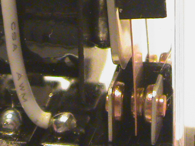
Relay contact close-up. Photo by Pineywoodsdavid, Wikimedia Commons, licensed under CC BY-SA 3.0. No changes made.
Contact life depends on the interaction between contact material, load waveform, voltage, operating frequency, environment, and coil behavior. TE Connectivity's contact-life guidance emphasizes that there is no universal contact material for every load. The safe comparison is always between your application envelope and the manufacturer's stated test condition.
AC and DC Contact Ratings Are Not Interchangeable
Alternating current passes through zero every half-cycle. That natural current zero can help an arc extinguish after contacts separate. Direct current has no repeating zero crossing, so an opening arc may continue longer. Contact gap, material, geometry, magnetic arc control, polarity, voltage, current, and load inductance all affect interruption.
A relay rated for a certain AC voltage and current may have a much lower DC rating-or no useful DC interruption rating at that voltage. This is why "250 VAC / 30 VDC" or similar markings must be read as separate conditions, not as equivalent power values.
DC selection checkpoint: record the maximum DC voltage, steady current, inrush, L/R or inductance, polarity, switching frequency, and required life. Then use an explicit DC make/break rating. Multiplying "maximum switching voltage" by "maximum switching current" usually creates a condition that was never approved.
How to Select a Relay for Each Load Type
1. Resistive Heaters
Resistive heaters and resistor banks are normally the simplest loads because current rises with applied voltage and turn-off energy is low compared with a coil. Still, check the maximum line voltage, true operating current, cold versus hot resistance, cycles per hour, enclosure temperature, terminal temperature, and required service life.
Use the relay's resistive make/break rating at the actual AC or DC voltage and verify electrical life at the planned switching rate. A relay may suit occasional heater control but become uneconomical for rapid temperature cycling. For frequent switching, compare an electromechanical relay with a correctly selected solid-state relay or contactor. An SSR also requires output-type matching, heat-sink calculation, leakage-current review, surge protection, and safe failure handling.
2. Solenoids, Valves, and Other Coils
An inductive load stores energy in its magnetic field. When the relay opens, the current tries to continue, raising voltage across the separating contacts. The result can be arcing, contact erosion, electromagnetic interference, and stress on nearby electronics. AC solenoids can also draw a high pull-in current until the armature is fully seated.
Ask the load supplier for pull-in current, holding current, coil voltage tolerance, release-time requirement, and-especially for DC coils-inductance or a measured decay waveform. Select against a published inductive rating and design suppression as part of the circuit:
- Flyback diode: effective for many DC coils, but it can slow release because current decays gradually.
- Diode plus Zener or TVS: allows faster decay at a higher controlled clamp voltage; check the relay, driver, coil insulation, and energy rating.
- RC snubber: can reduce arc energy and EMI in a properly designed AC or DC circuit, but adds leakage and a closing-current path.
- MOV or varistor: commonly considered for AC coils; confirm energy, aging, safety approval, leakage, and placement.
OMRON's suppression guidance says component choice and values depend on the load and should be confirmed experimentally. A suppressor does not make an undersized relay acceptable; make, carry, break, insulation, and thermal ratings still apply.

Solenoid valve, an example of an inductive load. Photo by ToT89, Wikimedia Commons, licensed under CC BY-SA 4.0. Displayed at a smaller size; no other changes made.
3. Motors
A motor's nameplate running current is only one input. Obtain starting current, locked-rotor or stall current, switching frequency, reversal or braking duty, phase count, power factor where relevant, and the required overload and short-circuit protection. A small DC fan, an AC fractional-horsepower motor, and a three-phase induction motor are different switching problems.
For most industrial motor-power circuits, a contactor or motor starter selected for the motor duty is the clearer architecture. A relay can energize the lower-power contactor coil while the contactor handles line power. Direct motor switching may be valid for a small load only when the relay manufacturer publishes a matching motor-load rating and electrical-life evidence at the exact voltage and duty.
Do not improvise motor reversing with a changeover contact merely because it provides common, normally open, and normally closed terminals. Contact timing, break-before-make behavior, back EMF, interlocking, regeneration, and stall conditions must be engineered. Use a purpose-built reversing contactor system, H-bridge, or motor controller as appropriate.
4. Incandescent Lamps, LED Drivers, and Power Supplies
Incandescent and halogen lamps draw high cold-filament current. LED drivers, electronic ballasts, and AC-DC power supplies often use a bridge rectifier and bulk input capacitor. At turn-on, that capacitor can draw a short, steep surge. Contact bounce can apply the stress more than once near closure, so a 10 A resistive rating does not prove reliable switching of a 2 A driver.
Ask for the inrush peak, pulse duration, repetition rate, test voltage, and test method. If those data are unavailable, measure the finished circuit with suitable instruments. Cable resistance, source impedance, temperature, input limiters, and the number of parallel drivers can change the peak. Look for a published lamp, ballast, TV, capacitive, or inrush rating that matches the application. A TV rating is evidence for its defined tungsten-lamp test, not automatic approval for every electronic driver.
5. Capacitive Loads and Transformers
Capacitive input circuits are limited largely by capacitance, initial charge, source impedance, wiring resistance, and the point in the AC waveform when the contact closes. Transformer magnetizing inrush depends on supply phase and residual core flux, so identical operations can produce different peaks. Steady watts or VA do not describe either event well.
For capacitive loads, document capacitance, initial voltage, maximum supply voltage, wiring impedance, peak current, pulse duration, and switching sequence. For transformers, request primary inrush data under the real energization conditions. The system may need an inrush-rated relay, NTC/resistor precharge and bypass, controlled switching, a purpose-built contactor, or another architecture. Verify restart behavior and fault protection as well as normal operation.
6. Low-Level and Dry-Circuit Signals
Low-level switching can fail for a different reason: the circuit may provide too little voltage or current to overcome films, oxidation, contamination, or unstable contact resistance. A contact designed for power switching is not automatically reliable for millivolt or milliamp sensor, analog, measurement, or PLC input signals.
Use the manufacturer's stated minimum applicable load, contact material, sealing, resistance data, and reliability information. Gold flash or gold plating can help in the right design, but it is not a universal solution. Confirm the real signal range, wetting current, environment, dormant periods, and whether the same contact will ever switch a higher-energy load.
Coil Drive, Contact Form, and Installation Still Matter
Correct contact ratings cannot compensate for poor coil drive. The coil must pick up and remain seated at the worst control voltage, ambient temperature, supply tolerance, and transient condition. Chatter or incomplete seating can damage contacts rapidly. TE Connectivity's coil-drive guidance recommends validating the final assembly because supply wiring, temperature, and control behavior affect contact performance.
| Feature | Check | Failure prevented |
|---|---|---|
| Coil | AC/DC type, pickup and release range, coil power, duty | Chatter, weak closure, overheating |
| Contact form | NO/NC/changeover, poles, normal-state safety, timing | Wrong logic, unsafe transitions, cross-conduction |
| Contact variant | Exact material and suffix for power, inrush, or low-level duty | Welding, erosion, unstable signal |
| Mounting and terminals | PCB/socket/panel format, conductor size, terminal temperature | Heating, loose connections, service mismatch |
| Insulation and approvals | Creepage, dielectric, pollution conditions, required marks | Unsafe separation or market non-compliance |
| Environment | Temperature, vibration, humidity, contamination, enclosure | Corrosion, coil problems, shortened life |
When to Use a Relay, Contactor, SSR, or Dedicated Driver
The correct solution is sometimes a different switching architecture rather than a larger relay. Choose according to the load energy, switching frequency, protection needs, thermal limits, diagnostics, service strategy, and predictable failure mode.
| Architecture | Strong fit | Qualification needed |
|---|---|---|
| Electromechanical relay | Modest load with a matching published rating and manageable duty | Inrush, arcing, electrical life, coil drive, temperature |
| Relay driving a contactor | Motor power, larger heaters, multi-pole line switching | Select/protect both devices; suppress the contactor coil correctly |
| Solid-state relay | Frequent AC resistive switching, silent operation | Heat sink, derating, leakage, surge, output type, fault behavior |
| Transistor or MOSFET driver | DC coils and logic-controlled loads | SOA, clamp energy, thermal design, diagnostics |
| Motor controller or drive | Reversing, braking, variable speed, frequent starts | Motor duty, protection, EMC, safe control design |

Solid-state relay example. Photo by W2000, Wikimedia Commons, licensed under CC BY-SA 4.0. No changes made.
Safety boundary: A standard relay is not automatically a safety relay, safety contactor, motor starter, overcurrent protective device, or hazardous-location component. For safeguarding, emergency stop, hazardous energy, motor protection, hazardous areas, or regulated equipment, use the applicable standards, certified components, and a qualified system risk assessment.
A Repeatable Seven-Step Relay Selection Workflow
- Classify the load. State whether the relay switches the load directly or only energizes another device's coil.
- Define the complete electrical envelope. Include minimum/maximum voltage, AC or DC, steady current, inrush peak and duration, power factor or L/R, turn-off transient, and abnormal states.
- Define duty and life. Record operations per hour, on/off time, total required cycles, ambient temperature, enclosure, and acceptable failure behavior.
- Read the exact datasheet variant. Check make, carry, break, rated load, electrical life, minimum load, coil, contact form, insulation, terminal, mounting, and approval conditions.
- Compare like with like. If the datasheet has no matching motor, lamp, capacitive, transformer, inductive, or DC evidence, mark the application unverified. Do not borrow the resistive rating.
- Design the surrounding circuit. Select coil drive, suppression, overcurrent protection, inrush control, wiring, heat management, and-if needed-a contactor or dedicated driver.
- Validate the finished assembly. Capture make/break waveforms and temperature at worst line, load, ambient, and switching duty. Test representative samples long enough to expose cumulative wear.
Contact damage can accumulate silently. Welding, pitting, material transfer, carbon deposits, and rising contact resistance may appear after thousands of operations rather than during a short bench check. TE Connectivity's contact-arc explanation shows why arcing erodes material and why DC is especially difficult to interrupt. Actual-load endurance testing is usually less costly than a field replacement program.
Example: Why a 10 A Relay Can Fail on a 2 A LED Supply
Consider a packaging machine with a 2 A LED power supply. A buyer chooses a relay marked 10 A because the running current appears comfortably below the contact rating. The machine passes commissioning, but some relays later stick closed after repeated power cycling.
The likely problem is not continuous overload. The power supply's input capacitor creates a high, short closing surge; contact bounce can repeat the stress. The correct diagnostic is to measure the inrush waveform with the exact supply, cable, line voltage, temperature, and switching sequence, then compare it with an expressly tested inrush category and life target.
The corrective action could be an inrush-rated relay, an input limiter or precharge circuit, controlled switching, a different power supply, a contactor, or a revised architecture. The lesson is simple: running current is not make current.
Troubleshooting Symptoms by Load Stress
| Symptom | Likely mechanism | Next check |
|---|---|---|
| Contacts weld closed | High make inrush from lamp, capacitor, transformer, or stalled motor | Capture inrush and compare with a tested inrush rating. |
| Intermittent load | Inductive erosion/carbonization or low-level contact film | Measure turn-off transient and test at the actual signal level. |
| Relay or terminal runs hot | Carry current, terminal resistance, or enclosure temperature | Log coil, contact, terminal, and ambient temperatures. |
| Life far below datasheet | Actual waveform/duty does not match the published test | Compare voltage, load type, inrush, cycles, and temperature. |
| Solenoid releases slowly | Flyback diode extends current decay | Measure release time; validate a higher-voltage clamp if needed. |
| Relay chatters | Coil undervoltage, wrong coil, or control-supply dip | Log voltage at the coil terminals during load events. |
RFQ Checklist for Relay Suppliers
"24 V relay, 10 A" is not enough for a defensible selection. A useful RFQ lets the supplier identify the contact and coil variant-or recommend a different device class-without guessing the load.
- Load: heater, solenoid, motor, lamp, LED driver, transformer, capacitor, signal, or mixed load.
- Electrical conditions: AC/DC, nominal and maximum voltage, steady current, peak inrush, pulse duration, repetition, power factor or L/R.
- Duty: operations per hour/day, on/off duration, total life target, and abnormal switching events.
- Relay configuration: contact form, poles, coil voltage, mounting, terminals, sealing, size, and approvals.
- Environment: ambient range, humidity, contamination, vibration, altitude, enclosure, and service access.
- Protection: current suppression, inrush control, fusing, overload protection, and required release time.
- Acceptance evidence: exact ordering code, load-specific electrical-life data, test circuit, sample quantity, traceability, and change control.
Ask whether the offered part has an electrical-life rating for your load category, voltage, and switching rate. Request the full suffix: one series may contain different contact materials or variants for power, low-level, motor, or high-inrush service.
Need help matching a relay to a real load?
Send QIANJI the load voltage, AC/DC type, steady current, inrush waveform, switching frequency, coil voltage, environment, lifetime target, and required approvals. The more complete the load data, the more meaningful the product recommendation and sample-validation plan.
Browse verified QIANJI categories: power relays, general-purpose relays, PCB relays, and solid-state relays. A category page is a starting point; the exact model still needs application-specific confirmation.
Frequently Asked Questions
Can I use a 10 A relay for any load below 10 A?
No. The 10 A value may describe a resistive carry or switching condition. Motors, transformers, lamps, capacitive inputs, and solenoids can create a much harder make or break event. Check the exact load category, voltage, waveform, and electrical-life condition.
What matters most for an inductive load?
There is no single number. Check pull-in and hold current, the make and break capability at actual voltage, power factor or L/R behavior, turn-off transient, suppression, release time, and loaded electrical life. Opening stress is often decisive because the load tries to maintain current.
Why do relay contacts weld on an LED driver?
Many LED drivers contain an input capacitor that draws a steep charging pulse at turn-on. The pulse can be far above running current, and contact bounce may repeat it. Measure the exact driver bank and select using relevant inrush evidence.
Should every DC solenoid use a flyback diode?
A diode is effective for many DC coils, but it can slow mechanical release. Whether that delay is acceptable depends on the function. Select the clamp with the coil, relay, driver, EMC target, insulation, and safety timing, then test the finished circuit.
Why is a relay's DC rating often lower than its AC rating?
AC current crosses zero naturally, which can help an arc extinguish. DC has no repeating current zero, so the arc can continue as contacts separate. Use an explicit DC switching rating for the actual voltage, current, inductance, polarity, and suppression.
When should a relay drive a contactor?
Use this architecture for motor power, higher currents, multi-pole line power, demanding duty, or loads needing coordinated overload and short-circuit protection. The interface relay still needs a suitable rating and suppression for the contactor coil.
Can a power relay switch a low-level sensor signal?
Not automatically. Very small signals can be disrupted by contact film, contamination, or unstable resistance. Check the minimum applicable load and contact construction, and test it with the real signal circuit and environment.
Does a snubber make an undersized relay safe?
No. Suppression can reduce transient voltage, arc energy, and EMI, but it does not create the required make, carry, break, insulation, or thermal capacity. Select an adequately rated device first and validate the suppression network separately.
Final Recommendation
The most reliable selection habit is to stop asking only "How many amps is the load?" and ask instead: "What does the contact see when it makes, carries, and breaks this load throughout the required life?" Classify the load, obtain the real waveform, select against matching published evidence, protect inductive circuits intentionally, verify the coil, and test the finished assembly. If the duty is high-energy, motor-related, frequent, safety-relevant, or difficult to interrupt, change the architecture rather than stretching a general relay beyond its evidence.
Technical References
- IEC 61810-1:2015+AMD1:2019 CSV - electromechanical elementary relay scope and general/safety requirements.
- Panasonic Industry: Relays Cautions for Use - load behavior, typical inrush ranges, and actual-circuit measurement.
- OMRON FAQ02804 - diode, CR, and varistor suppression guidance.
- OMRON Fundamentals of Relays - contact operation and application fundamentals.
- TE Connectivity: Relay Contact Life - contact material and load/life interactions.
- TE Connectivity: Contact Arc Phenomenon - arcing, erosion, material transfer, and DC interruption.