


Short answer: IEC/UL 61810-1 gives OEM teams a component-level framework for evaluating electromechanical elementary relays. It does not approve the finished machine, appliance, controller, or panel. A sound buying decision still has to connect the exact relay model to its certification evidence, conditions of acceptability, real contact load, coil circuit, insulation system, mounting interface, application testing, and change-control plan.
OEM decision rule
Specify the application first. Then use IEC/UL 61810-1 evidence to screen the correct relay. Never select a relay from a standard name, approval logo, coil voltage, and headline current alone.
What OEM Buyers Need to Know First
- IEC 61810-1 is a relay component standard. Its scope covers electromechanical elementary relays incorporated into low-voltage equipment, up to 1,000 V AC or 1,500 V DC.
- UL Recognition is not end-product Listing. A Recognized Component is intended for use inside a larger certified product and may have specific conditions of acceptability.
- A contact rating is conditional. AC or DC voltage, load type, inrush, power factor or L/R, switching frequency, ambient temperature, and required operations all affect suitability.
- The relay body is only part of the insulation system. PCB tracks, pads, sockets, terminals, wiring, contamination, altitude, enclosure geometry, and the end-product standard also matter.
- The exact suffix matters. Coil, contact material, terminal, seal, mounting option, production site, and certification coverage can change between variants in one family.
- Application testing closes the gap. Representative assemblies should be tested at justified worst-case electrical, thermal, environmental, and mechanical conditions.
| IEC/UL 61810-1 evidence can support | The OEM must still establish |
|---|---|
| A common component-level basis for relay construction, functional requirements, safety-related requirements, and type tests | The applicable machine, appliance, panel, medical, building-control, transport, or other end-product compliance route |
| Evidence tied to a relay model or evaluated family | Whether the exact purchasable suffix, factory, marking, and intended installation are covered |
| Published contact, coil, insulation, terminal, environmental, and endurance information | Performance under the OEM's real load waveform, driver, duty cycle, temperature, PCB or socket, and enclosure |
| A useful input to component approval and certification work | Final-product construction review, application tests, production controls, traceability, and approved change management |
What IEC 61810-1 Covers-and What It Does Not
IEC 61810-1:2015 + Amendment 1:2019, Edition 4.1, applies to electromechanical elementary relays for incorporation into low-voltage equipment. IEC describes it as a general and safety requirements standard whose compliance is checked through the specified type tests. The IEC record also says that an application with additional requirements should be assessed under the relevant application standard.
That boundary is important. The standard can help an OEM answer, "What evidence exists for this relay component?" It cannot, by itself, answer, "Is our finished product compliant in every target market?" The final answer may depend on an appliance, industrial control,
machinery, medical, railway, transport, building-control, or other product standard, together with national differences and the certification body's investigation.
The North American route must also be identified precisely. The current ANSI/UL 61810-1 Second Edition was published and ANSI approved on June 15, 2026. UL states that it adopts IEC 61810-1 Edition 4.1 and provides a national-differences document. For an RFQ or compliance matrix, write the required standard, edition, market, and certification path instead of using the vague phrase "IEC/UL approved."
Do not publish a blanket claim. A supplier's statement that a relay family is "UL," "IEC," or "compliant" is not enough. Verify the exact model, suffix, manufacturer, production source, certification status, ratings, and use conditions through current controlled documents and the relevant official database.
Standard, certification, recognition, and listing are different
| Term | What it tells the buyer | What to verify |
|---|---|---|
| Standard | The requirements and test framework used for an evaluation | Number, edition, amendment, national differences, and applicability |
| Certificate or report | Evidence issued for identified products within a defined scope | Issuer, status, model list, factory, ratings, dates, and limitations |
| UL Recognized Component | A component evaluated for factory installation in a larger UL Certified product | Product iQ record, file/category, exact model, and conditions of acceptability |
| UL Listed product | A complete product or equipment evaluated for its intended field use | The complete product, installation instructions, market, and certification record |
UL explains that Recognized Components are assessed for use within a larger certified end product and are subject to conditions of acceptability. Those conditions can limit temperature, wiring, enclosure, mounting, or other use details. Recognition can simplify end-product evaluation, but it is not certification of a complete standalone machine or panel.
Why the Exact Relay Variant Matters
Relay families often contain several coil voltages, contact forms, contact materials, terminal options, enclosures, seals, and mounting arrangements. Two products may look interchangeable while having different operating voltage, release voltage, coil power, contact gap, load capability, insulation construction, or certification coverage. A family brochure is therefore not a controlled approval record.
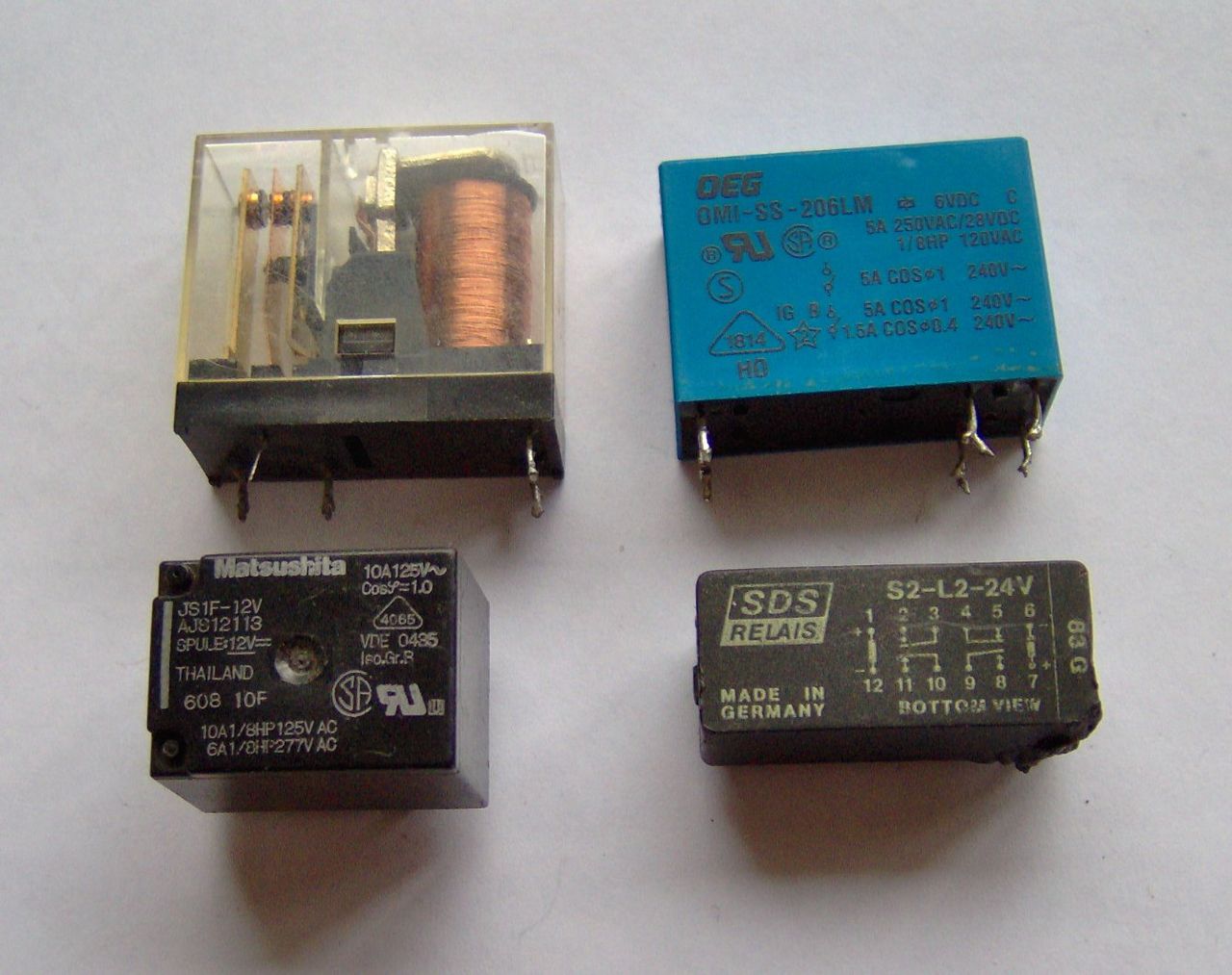
Different relay packages can hide significant electrical and mechanical differences. Photo: FDominec / Wikimedia Commons, licensed under CC BY-SA 3.0. No changes made.
Freeze the complete ordering code on the approved parts list. The approval record should link that code to the current data sheet, terminal drawing, certification evidence, conditions of acceptability, approved manufacturing location, application test report, and incoming inspection criteria. If a suffix changes, reopen the mapping before production use.
QIANJI offers several relay categories for different mounting and load needs. Buyers can compare the general ranges on the power relay and PCB relay pages, but final selection should always be based on the exact part data and the real application.
Step 1: Translate the Application into a Relay Requirement
A useful relay specification begins with the circuit and mission profile, not a catalogue filter. Engineering, compliance, quality, and sourcing should agree on the following inputs before requesting quotations:
- target countries and applicable end-product standards;
- contact form, pole count, and required normal state;
- AC or DC working voltage at the contacts;
- normal current, make current, break current, inrush peak, waveform, and duration;
- load type, power factor or L/R time constant, and suppression at the load;
- switching frequency, expected operations, on-time, and required service life;
- minimum load if the contacts also switch low-level signals;
- coil supply range at the relay pins, driver topology, suppression, and timing needs;
- ambient and internal enclosure temperature, humidity, contamination, altitude, shock, and vibration;
- PCB, socket, quick-connect, wiring, terminal, or bracket interface;
- failure consequences, diagnostic coverage, maintenance, and replacement strategy.
A statement such as "24 VDC coil, SPDT, 10 A, UL required" leaves the most important selection variables undefined. It can lead several suppliers to quote technically different relays against what appears to be the same RFQ.
Step 2: Treat Contact Ratings as Test Conditions
A relay marked 10 A is not suitable for every 10 A load. Contact performance depends on the voltage, current, circuit type, make and break behavior, switching rate, ambient conditions, contact material, and the acceptance criterion used in the test. DC interruption and inductive or capacitive loads can be much more demanding than a similar steady resistive current.
| Load | Main contact risk | Buyer action |
|---|---|---|
| Resistive heater | Thermal current and terminal/PCB temperature rise | Confirm voltage, current, duty, ambient, enclosure heat, and life at the stated condition |
| Motor or contactor coil | Inrush, low power factor, bounce, and inductive break energy | Measure make/break waveforms and use documented inductive or motor-load evidence |
| Lamp or capacitive input | High, short-duration inrush and contact welding | Define peak, duration, repetition, and precharge or limiting method |
| DC solenoid or valve | Sustained arc and suppression-dependent release behavior | Specify DC voltage, current waveform, L/R, suppression, and required release time |
| Low-level signal | Surface films, contamination, and unstable contact resistance | Check minimum-load guidance, contact material, environment, and resistance after cycling |
Use real waveforms, not labels
Measure the load at the relay terminals where practical. Record the initial inrush, steady current, break current, transient voltage, power factor or L/R, and switching sequence. Test with the actual suppression network and representative wiring. This makes the supplier's rating evidence comparable to the OEM duty and gives the endurance test a reproducible basis.
Step 3: Verify the Coil, Driver, and Suppression Together
Nominal coil voltage is only a starting point. The relay must operate and release correctly at the voltage actually present at its pins across supply tolerance, driver drop, wiring loss, cold and hot coil resistance, enclosure temperature, and the number of simultaneously energized coils.
Coil suppression changes current decay. A diode across a DC coil may reduce driver stress but can slow release. That delay can affect contact arcing, mechanical sequencing, interlocks, and diagnostic timing. A zener, TVS, resistor-capacitor network, or another method may behave differently. Use only a suppression approach compatible with the relay and driver, and confirm release time in the real circuit.
| Coil check | Required evidence | Typical failure if missed |
|---|---|---|
| Operate margin | Minimum pin voltage at worst supply, driver, wiring, and hot-coil condition | Chatter or failure to pull in |
| Release margin | Maximum residual voltage and release behavior with suppression fitted | Slow or incomplete release |
| Coil heating | Power tolerance, duty, hot ambient, nearby heat, and simultaneous-coil test | Excess temperature or shortened life |
| Driver protection | Measured transient and verified component ratings | Driver damage or EMI problems |
Step 4: Build Insulation Coordination Around the Whole Assembly
A published dielectric-withstand value is not a working-voltage rating and does not define the finished PCB clearance or creepage requirement. Insulation coordination starts with the applicable end-product method and includes working voltage, transient overvoltage, insulation type, pollution degree, material group, altitude, clearances, creepage distances, solid insulation, and accessible circuits.
The current IEC consolidated reference is IEC 60664-1:2020 + Amendment 1:2025. In North American work, UL 840 provides an insulation-coordination approach where the applicable product standard permits it. The responsible compliance engineer should determine which method controls the design.
Review the complete separation path:
- inside the exact relay variant;
- between relay pins and under the relay body;
- across PCB pads, tracks, vias, solder, and exposed copper;
- through the selected socket, terminals, wire preparation, and connector;
- around contamination, flux residue, moisture, dust, coating gaps, and enclosure surfaces;
- after endurance, thermal stress, vibration, board flex, and foreseeable service work.
Important: Do not claim creepage or clearance credit for coating unless the controlling standard, coating system, production process, coverage, inspection, repair method, and qualification evidence support that credit.
Step 5: Check the PCB, Socket, Terminal, and Mechanical Interface
Many failures attributed to the relay originate at the interface: overloaded PCB tracks, hot terminals, insufficient solder, wrong footprints, board flex, flux residue, loose sockets, poor quick-connect retention, unsupported cable mass, or inadequate mounting. These are design-verification issues, not details to resolve after purchasing selects a model.

Microscopic inspection can reveal dimensional and soldering issues at the component interface. Photo: Gabriela P. / Wikimedia Commons, licensed under CC BY 4.0. No changes made.
| Interface | Review | Verify on the assembly |
|---|---|---|
| PCB footprint | Bottom-view pin map, tolerances, pin shape, keep-outs, and spacing routes | First-article fit, correct nets, solder geometry, and inspection access |
| High-current path | Copper thickness, trace width, vias, pads, terminals, and adjacent heat sources | Temperature rise and voltage drop at worst justified load and ambient |
| Socket or terminal | Exact mating part, plating, wire range, torque, retention, and assembly tooling | Mating, pull or torque, thermal behavior, dielectric separation, and error prevention |
| Mechanical mounting | Orientation, supports, bracket stiffness, locking, cable force, and shipping loads | Representative vibration, shock, handling, and post-test functional inspection |
Step 6: Demand a Traceable Evidence Package
A credible evidence package lets the OEM identify the component, compare it with the requirement, and keep control after production starts. Request it during quotation and sample approval-not after a customer audit exposes a gap.
| Evidence | Minimum content | Red flag |
|---|---|---|
| Controlled data sheet | Exact code, suffix map, coil/contact options, ratings, dimensions, terminals, environment, approvals, revision, and date | Family brochure with generic ratings and no revision |
| Certification evidence | Issuer, standard/edition, manufacturer, file or certificate, models, source, status, and limitations | A logo image or certificate for another model or factory |
| Conditions of acceptability | Temperature, mounting, wiring, construction, ratings, combinations, and use restrictions where applicable | Assuming recognition has no conditions |
| Test report | Method, edition, specimens, circuit, load, environment, sample size, results, failures, deviations, and criteria | One-line "pass" statement with no setup or limits |
| Traceability and PCN | Lot/date mark, factory, controlled materials/processes, inspection plan, and written change-notification commitment | No link between received product, qualified samples, and current documents |
For a UL Recognized Component, verify the current official record and reconcile the manufacturer name, exact model, file/category, ratings, and conditions of acceptability. UL identifies Product iQ as the official route for checking certification information. Screenshots copied between suppliers are not a reliable substitute for the current record.
Step 7: Run a Risk-Based OEM Qualification
The test depth should match the risk. A mature resistive-load application operating well within documented conditions may need focused evidence review, dimensional checks, pilot-build verification, thermal confirmation, and incoming controls. High-voltage DC, repetitive inrush, motors, frequent switching, safety-related outputs, difficult service access, or expensive field failures justify deeper endurance, abnormal-condition, environmental, and compliance work.
- Freeze the intended use. Record the schematic, contact circuits, coil circuit, waveform, cycles, ambient, installation, markets, standards, and measurable acceptance criteria.
- Map the exact part. Reconcile the full suffix with the current data sheet, drawings, certification evidence, conditions of acceptability, and factory information.
- Characterize samples. Check dimensions, pin fit, markings, coil operation and release, contact resistance, and basic function.
- Test the application. Use the representative PCB, socket, harness, enclosure, driver, suppression, load, duty, and justified worst-case ambient.
- Review boundaries. Consider supply extremes, brownout, stalled or abnormal loads, suppression failure, contamination, heat, installation error, and other foreseeable conditions from the safety analysis.
- Qualify production. Use commercial-tooling samples, define inspection and traceability, retain reference samples, and confirm process controls.
- Release with change control. State which product, material, process, site, tooling, test, document, or certification changes require review and requalification.
IEC 61810-2 provides a statistical framework for obtaining relay reliability characteristics from endurance tests. It does not turn a catalogue operation count into a guaranteed field lifetime for every mission profile. Define the load, failure criterion, sample plan, confidence objective, environment, and operating profile before using reliability data in a system calculation.
If the architecture requires forcibly guided, or mechanically linked, contacts, IEC 61810-3 adds special requirements and tests to IEC 61810-1. Such a relay may support fault monitoring, but it does not by itself create a Safety Integrity Level, Performance Level, or complete functional-safety system.
Alternative Sources Are New Components Until Proven Equivalent
A footprint-compatible relay with the same coil voltage, contact form, and current label may still differ in operate/release margins, coil power, contact material, internal spacing, terminal strength, contact gap, seal, inrush performance, endurance, factory control, or certification conditions. Approving an alternative by catalogue comparison alone transfers hidden risk into production.
| Change | Minimum response | Likely verification |
|---|---|---|
| New manufacturer or relay family | Full requirement and evidence comparison with compliance approval | Fit, coil, contact, thermal, endurance, insulation, and system review |
| Coil, contact, terminal, seal, or housing suffix | Part-number and certification-coverage mapping before use | Targeted electrical, fit, thermal, and environmental checks |
| Factory, material, process, tooling, or test-method change | Written PCN, change package, source traceability, and risk review | First-lot control, audit, dimensional or delta testing as justified |
| New load or operating condition | Reopen the application requirement and safety analysis | Application endurance, thermal, insulation, timing, or abnormal-condition testing |
OEM Relay RFQ Checklist
Use this checklist in the design specification, sourcing brief, supplier questionnaire, or quality agreement. It should be reviewed across electrical engineering, compliance, quality, and sourcing.
- Product and market: equipment type, target countries, end-product standard, installation, normal and abnormal use, and service-life objective.
- Exact relay: contact form, poles, contact material where relevant, coil type and voltage, complete suffix, terminals, mounting, enclosure, and seal.
- Contact duty: AC/DC voltage, make/break current, inrush waveform, load type, power factor or L/R, minimum load, switching rate, and required operations.
- Coil and driver: pin-voltage range, driver topology, suppression, operate/release timing, duty, simultaneous-coil population, and hot/cold conditions.
- Insulation: working and impulse requirements, controlling standard, spacing method, altitude, pollution, PCB, socket, terminals, and wiring.
- Mechanical and environmental: ambient, humidity, condensation, corrosion, mounting, shock, vibration, cable force, packing, and transport.
- Compliance evidence: exact standard and edition, current file/certificate, covered models, factory, status, ratings, and conditions of acceptability.
- Quality controls: marking, lot traceability, control plan, inspection data, sample retention, corrective action, and counterfeit prevention.
- Change control: approved source and site, PCN lead time, controlled changes, deviation process, and requalification responsibility.
Useful purchase-specification principle
Require written notice and buyer approval before changes to the approved manufacturer, suffix, factory, internal design, contact system, coil, terminal or plating, housing material, tooling, process, test method, marking, or certification status. Let the buyer require evidence review, delta testing, or requalification before shipment.
Frequently Asked Questions
Is IEC 61810-1 the same as UL 61810-1?
They are closely related, but the exact edition and national differences matter. As checked in August 2026, ANSI/UL 61810-1 Second Edition adopts IEC 61810-1 Edition 4.1 and has a separate national-differences document. State the market path and required evidence in the RFQ.
Does a UL Recognized relay make my product UL Listed?
No. Recognition applies to a component intended for use in a larger certified product and may include conditions of acceptability. Listing or other finished-product certification evaluates the complete construction and intended installation.
Can any 10 A relay switch a 10 A load?
No. The rating must match AC or DC voltage, load type, make and break conditions, inrush, power factor or L/R, switching frequency, temperature, and required operations. Always compare the supplier's stated test condition with the real waveform.
Does dielectric withstand define PCB creepage and clearance?
No. It is one piece of component evidence. The complete insulation design depends on working voltage, transients, insulation type, pollution, altitude, materials, PCB/socket/wiring geometry, and the applicable end-product method.
What should I request before approving a second source?
Request the exact data sheet, drawings, certification record and model coverage, conditions of acceptability, coil/contact/insulation data, factory and traceability details, change-control commitment, and test evidence matched to the application. Then complete a risk-based fit, electrical, thermal, endurance, and compliance review.
When is a forcibly guided contact relay needed?
Use it when the application or safety architecture specifically requires mechanically linked contact behavior and the exact relay is evaluated to the relevant special requirements. The relay supports the architecture; it does not replace system-level fault analysis and functional-safety validation.
Final Recommendation
For each approved IEC/UL 61810-1 relay, freeze the complete evidence chain: supplier, exact model and suffix, coil, contacts, terminals, mounting interface, load conditions, PCB or socket design, certification record, conditions of acceptability, qualification reports, production source, incoming controls, and PCN rules. This converts a seemingly interchangeable part into a controlled reliability and compliance component.
If you are comparing a power relay or PCB relay for an OEM project, send QIANJI the real load waveform, coil circuit, switching rate, ambient, installation, target markets, and evidence requirements. The team can then help narrow the part options and prepare the exact technical information needed for your engineering review. Submit your relay requirements to QIANJI.
This guide is for engineering and sourcing education. It does not replace the purchased standards, the certification body's current record, the selected relay manufacturer's controlled data, or a qualified compliance review for a specific product and market.
Technical References
- IEC 61810-1:2015 + AMD1:2019, Edition 4.1 - official IEC scope and publication status.
- ANSI/UL 61810-1, Second Edition - official UL publication date, scope, IEC adoption, and national-differences information.
- UL Component Recognition Classification - purpose, conditions of acceptability, Product iQ, and end-product boundary.
- UL component testing and certification - difference between Recognized Components and Listed products.
- IEC 60664-1:2020 + AMD1:2025 - current consolidated IEC insulation-coordination reference.
- UL 840 - insulation coordination including clearances and creepage distances.
- IEC 61810-2:2017 - endurance-test-based reliability evaluation using statistical methods.
- IEC 61810-3:2015 - relays with forcibly guided or mechanically linked contacts.