

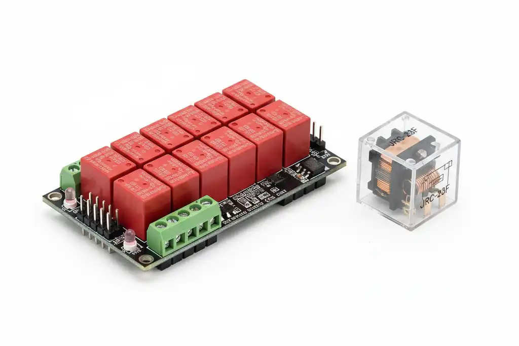
Many electronics projects face a common challenge. You need to control a high-voltage AC device, like a household lamp or powerful fan, using a low-voltage DC signal from a microcontroller like an Arduino or Raspberry Pi. These two electrical worlds cannot meet directly without causing damage.
The fundamental solution is the relay. It's an electromechanical switch that provides complete electrical isolation.
This brings every maker, engineer, and hobbyist to a critical decision point. Should you use a bare, standalone individual relay? Or should you opt for a convenient, pre-assembled relay module?
The answer is straightforward at a high level. A relay module is an integrated, "plug-and-play" circuit board designed for immediate use. An individual relay is the core component itself. It requires you to design and build the necessary supporting circuitry.
This guide will provide a deep dive into each option. We will examine the anatomy of an individual relay and detail the circuitry needed to make it work. We'll unpack the components of a relay module and conduct a head-to-head comparison. Finally, we will offer application-specific advice to help you make the definitive choice for your project.
Anatomy of an Individual Relay
Before we can appreciate the value of a relay module, we must first understand the foundational component it is built around. At its core, an electromechanical relay is a tiny, electrically operated switch.
It uses a small amount of power in one circuit (the control circuit) to switch a much larger amount of power in another circuit (the load circuit). All while keeping them completely isolated from each other.
The internal workings of a standard individual relay are elegant in their simplicity. They consist of a few key parts. Understanding these is essential for anyone working with them directly.
Coil: This is an electromagnet. When current flows through the coil, it generates a magnetic field. This is the "input" side of the relay.
Armature: This is the moving mechanical part of the switch. It is attracted by the magnetic field of the energized coil, causing it to pivot and move the contacts.
Contacts: These are the actual switch components that open or close the load circuit. They are connected to external terminals.
COM (Common): This is the terminal that is switched between the other two contacts. Your load's power source is typically connected here.
NO (Normally Open): This contact is disconnected from the Common terminal when the relay coil is not energized. The circuit is open by default.
NC (Normally Closed): This contact is connected to the Common terminal when the relay coil is not energized. The circuit is closed by default.
A crucial point to understand is that this component, the individual relay, cannot be safely or directly connected to a sensitive microcontroller pin. Doing so is a recipe for failure. This leads us to the complexities of the DIY path.
The DIY Individual Relay Path
Using an individual relay requires more than just the component itself. It demands the design and assembly of a dedicated "driver circuit." This circuit acts as the necessary intermediary between your low-power microcontroller and the relay's coil.
There are two primary, non-negotiable reasons why this driver circuit is essential. Neglecting either will, at best, result in a non-functional circuit. At worst, it will permanently destroy your microcontroller.
First, the issue of current amplification. A typical microcontroller I/O pin, such as those on an Arduino Uno, can safely source or sink only a small amount of current. Usually around 20-40mA. A relay's coil often requires significantly more current to generate a strong enough magnetic field to activate the armature. Anywhere from 50mA to over 100mA is common.
A transistor, such as an NPN Bipolar Junction Transistor (BJT) like the 2N2222 or a logic-level MOSFET, must be used. It acts as a digital switch. It uses the tiny current from the microcontroller pin to control the much larger current flow required by the relay coil.
Second, and arguably more critical, is the need for back-EMF protection. The relay's coil is an inductor. When you de-energize it by cutting the current, the collapsing magnetic field induces a large, sudden voltage spike in the reverse direction.
This phenomenon, known as back-EMF (electromotive force), can reach hundreds of volts. It will instantly destroy the sensitive output transistor on your microcontroller if not properly managed.
To combat this, a "flyback diode" (also called a snubber or freewheeling diode) is placed in parallel with the relay coil. It is oriented to block current during normal operation but provides a safe path for the back-EMF induced current to circulate and dissipate harmlessly. This protects your control electronics.
Building this circuit involves connecting the microcontroller pin to the base of the transistor through a current-limiting resistor. You connect the transistor's emitter to ground and place the relay coil between the positive power supply and the transistor's collector. The flyback diode is then connected across the coil's terminals, with its cathode (the striped end) facing the positive supply. This is the minimum viable circuit for safely driving a relay.
The Integrated Relay Module
The relay module is the elegant, pre-packaged solution to all the challenges just described. It takes the individual relay and the necessary driver circuit and integrates them onto a single, convenient Printed Circuit Board (PCB).
Physically, a relay module is a small board, often blue or red. It features the relay itself, a set of screw terminals for the high-power load, and a row of header pins for easy connection to a microcontroller.
When we unpack what's on a typical relay module, we find all the components of the DIY driver circuit, plus a few valuable extras that enhance usability and safety. This integration is the core value proposition of the module.
The Relay Itself: The core electromechanical switch is prominently featured on the board.
Driver Transistor: Tucked away on the PCB is the transistor (BJT or MOSFET) that performs the necessary current amplification.
Flyback Diode: The essential protection diode is always included, placed right next to the relay coil to protect the driver circuit.
Opto-isolator (Optional but common): Many quality modules include an opto-isolator. This component provides an even higher level of electrical isolation by using an internal LED and a phototransistor to transmit the control signal via light. It creates a complete electrical air gap between your microcontroller and the relay's driver circuit, offering superior protection against noise and voltage spikes.
Indicator LEDs: Modules almost always include at least two LEDs. One indicates that the module has power (VCC), and the other lights up when the relay is activated. This provides immediate visual feedback on the relay's status.
Input Pins (VCC, GND, IN): A simple 3-pin header allows for a clean and simple connection to your microcontroller's power, ground, and signal pins.
Screw Terminals (COM, NO, NC): These robust terminals provide a secure and reliable way to connect the heavier gauge wires required for your high-power AC or DC load.
The genius of the relay module is that it abstracts away the complexity of circuit design. It transforms a multi-component, error-prone assembly task into a simple, three-wire connection. This makes it incredibly fast and safe, especially for beginners.
Head-to-Head Comparison
Choosing between a relay module and an individual relay is a decision based on trade-offs. To make an informed choice, we need to compare them directly across several key factors that impact every project. From a simple hobbyist creation to a mass-produced commercial product.
The following table provides a clear, at-a-glance summary of how each option stacks up.
|
Feature |
Relay Module |
Individual Relay |
|
Ease of Use |
Excellent. Plug-and-play, minimal wiring. |
Low. Requires electronics knowledge, soldering. |
|
Speed of Prototyping |
Very Fast. Ideal for quick tests and projects. |
Slow. Circuit design and assembly take time. |
|
Cost (Per Unit) |
Higher. You pay for the convenience & components. |
Very Low. The component itself is cheap. |
|
Board Space/Footprint |
Larger. The PCB takes up more space. |
Minimal. Can be integrated tightly on a PCB. |
|
Flexibility/Customization |
Low. You are limited to the onboard components. |
High. Full control over component selection. |
|
Reliability |
Generally high, but depends on manufacturer quality. |
Depends entirely on your design and assembly skill. |
|
Troubleshooting |
Simpler. Often a faulty module is just replaced. |
More complex. Must debug the entire driver circuit. |
Let's elaborate on these points. The ease of use for a relay module cannot be overstated. It removes nearly all barriers to entry for controlling high-power loads. This makes it an incredible educational tool.
This directly translates to **speed of prototyping**. When you need to validate an idea quickly, spending hours designing, sourcing, and soldering a driver circuit is inefficient. A relay module allows you to go from concept to working prototype in minutes.
Cost is a nuanced factor. While the unit cost of an individual relay is pennies on the dollar compared to a module, this doesn't account for the cost of the other driver components, the PCB, and most importantly, your time. For one-off projects, the module is often more cost-effective overall.
Board space is a critical consideration for product design. A relay module is a bulky, general-purpose item. A custom-designed circuit using an individual relay can be made far more compact and integrated seamlessly onto a main product PCB.
Flexibility is the primary advantage of the DIY path. You can choose the exact relay for your needs. Perhaps a specific brand with a higher cycle rating, a latching relay for ultra-low power consumption, or a solid-state relay for silent, high-frequency switching. With a module, you are limited to the generic relay it comes with.
Reliability can be a double-edged sword. A well-manufactured relay module from a reputable supplier is generally very reliable. However, a poorly designed or assembled custom circuit can be a source of constant failure. Conversely, a professionally designed and manufactured custom circuit can be more reliable than a cheap, mass-produced module.
Finally, troubleshooting a relay module is simple. If it doesn't work, and the input signals are correct, you replace the module. Debugging a custom driver circuit requires an oscilloscope and a deeper understanding of electronics to pinpoint a failed transistor, a faulty diode, or a bad solder joint.
Application-Specific Choices
The theoretical pros and cons are useful, but the best choice often becomes clear when viewed through the lens of a specific application. The right answer for a hobbyist building an Arduino project is very different from that for an engineer designing a product for mass production.
For Hobbyists and Prototypers
For anyone working with platforms like Arduino, Raspberry Pi, or ESP32, the recommendation is clear and overwhelming: use a relay module.
The reasoning is multi-faceted. These modules are designed to work perfectly with the 5V or 3.3V logic levels and power capabilities of these boards. This eliminates guesswork and ensures compatibility right out of the box. More importantly, it provides a layer of safety, significantly reducing the risk of accidentally sending high voltage back into your delicate microcontroller.
In our experience teaching electronics workshops, we always use relay modules. It allows students to focus on the core logic of their project-the programming and system behavior-rather than getting bogged down in troubleshooting a transistor circuit. The goal is to get a project working quickly and reliably. The relay module is the fastest path to success.
For Automation Engineers
In the world of industrial automation and PLC systems, the landscape is more complex. Both individual relays and modules are used, but the "module" often takes on a more professional form.
Engineers frequently use DIN rail mountable relay modules. These are industrial-grade units designed for the harsh electrical environment of a control cabinet. They are standardized, easy to label, and can be swapped out in seconds without a soldering iron. This is critical for minimizing downtime.
These industrial modules are also designed for the common control voltage standard of 24V DC, unlike the 5V modules used by hobbyists. While a PLC's output card could theoretically drive an individual relay directly (as they have more robust outputs), using an interface relay module provides better isolation, easier serviceability, and a clear point of demarcation for troubleshooting. Individual relays are typically reserved for use on custom-designed interface PCBs within a larger system.
For Embedded Systems Designers
When the goal is to design a custom PCB for a commercial product that will be manufactured in quantity, the tables turn completely. Here, the individual relay and a custom-designed driver circuit are almost always the superior choice.
This is a critical distinction that many basic guides miss. For mass production, every decision is scrutinized for cost, space, and reliability.
First, cost optimization is paramount. At a scale of thousands or millions of units, saving even $0.50 per unit by using an individual relay and discrete components instead of a pre-built module translates into massive savings.
Second, space optimization is key. A custom circuit can be laid out on the main PCB to be far more compact than a bulky, off-the-shelf module. This allows for smaller and sleeker product designs.
Third, component selection becomes a strategic advantage. You are not stuck with a generic relay. You can specify a high-reliability relay from a premium manufacturer, a low-power latching relay to conserve battery life, or a specific solid-state relay to meet precise performance requirements for lifetime and switching speed.
Finally, by controlling the entire design and manufacturing process, from component selection to PCB layout and assembly, you have full control over the reliability and quality of the final product.
Your Final Decision Checklist
To synthesize everything we have covered, we can boil the decision down to a simple checklist. Ask yourself these five questions, and the right path for your specific project will become clear.
What is my electronics skill level? If you are a beginner or your primary focus is software, the relay module is your best friend. It guarantees a working hardware interface. If you are an experienced electronics designer comfortable with transistors, datasheets, and PCB layout, either option is on the table.
Is this a one-off project/prototype or for mass production? For any one-off project, personal hobby build, or initial prototype, the speed and convenience of a relay module are invaluable. For any product intended for mass production, the cost and space savings of an individual relay circuit are almost always mandatory.
How important is development speed vs. final unit cost? This is the classic trade-off. If getting a working system up and running as fast as possible is your top priority, choose the relay module. If minimizing the bill of materials (BOM) cost for a production run is the goal, the individual relay is the only way to go.
How tight are my space constraints? If you have ample space in your project enclosure, a relay module is perfectly acceptable. If you are designing a compact product where every square millimeter counts, you must design a custom circuit around an individual relay.
Do I need a specific type of relay? Standard relay modules almost always use a generic, single-pole double-throw (SPDT) electromechanical relay. If your application requires a special type, such as a latching (bi-stable) relay, a high-current solid-state relay (SSR), or a multi-pole relay (DPDT), you will almost certainly need to build a custom circuit around that specific individual relay.
The Right Tool for the Job
In the end, the debate between a relay module and an individual relay is not about which one is universally "best." It's about choosing the right tool for the job at hand.
The difference between relay modules and individual relays is a trade-off between convenience and customization. The relay module offers unparalleled convenience, safety, and speed. This makes it the ideal choice for beginners, educators, and rapid prototypers.
The individual relay, combined with a custom driver circuit, offers complete control, cost optimization, and space efficiency. This makes it the definitive choice for engineers designing commercial products for mass production.
By understanding the fundamental difference between a relay module and an individual relay, and by evaluating your project against the criteria of skill, scale, budget, and specific requirements, you are now equipped to select the right component with confidence. This ensures your project is both successful and efficient.
See also
How to distinguish between normally open and normally closed contacts of a relay
How to Choose the Right Automotive Relays and Fuse Boxes
Automotive Relay with Wiring Harness: Complete 2025 Installation Guide
Automotive Relays with Switches: 2025 Safety & Efficiency Guide