


Relay coils overheat when electrical input, operating time and surrounding heat push the winding above the limit for that exact relay. The most common causes are overvoltage, the wrong AC/DC coil, incorrect frequency or waveform, high local ambient temperature, continuous energization beyond the rated duty, poor airflow, an AC armature that does not fully close, damaged turns, and heat conducted from overloaded contacts or loose terminals.
A relay that feels warm is not automatically defective. Energized copper windings produce heat during normal operation. The correct question is whether the relay stays within its specified voltage, duty, ambient, mounting and temperature limits. A hand-touch test cannot answer that question, and there is no universal "safe relay temperature" that applies to every model.
Start with five facts: the complete relay and coil code, voltage measured at the coil terminals, AC/DC type and frequency or DC waveform, actual ON time, and local ambient temperature. Then check whether the armature pulls in fully and whether the contacts, socket or nearby equipment are adding heat.
Safety boundary: a hot relay can exist beside hazardous voltage, damaged insulation, a backfeed or welded contacts. A relay click does not prove that the load is isolated. Use qualified electrical personnel, the site's approved isolation and verification procedure, and correctly rated instruments. Do not repeatedly energize a swollen, melted, burnt-smelling or otherwise damaged device.
Relay Coil Overheating: Quick Diagnosis
|
Observed Pattern |
Likely Direction |
Best First Check |
|---|---|---|
|
Warm after long continuous energization, with normal operation and no damage |
Possibly normal self-heating, but thermal margin is not yet proven |
Verify the exact coil data, local ambient, duty, mounting and stabilized temperature |
|
Rapid temperature rise after replacement or wiring work |
Wrong coil voltage, AC/DC type, frequency, wiring or boost-and-hold behavior |
Read the full coil suffix and measure the waveform at the coil terminals |
|
Buzzing, chatter or failure to remain pulled in |
Supply dip, wrong frequency, dirty pole faces or mechanical obstruction |
Capture terminal voltage during the event and check full armature seating after isolation |
|
One relay is hotter than identical neighboring units |
Different duty, local airflow, connection heat, load heat or internal damage |
Compare voltage, current, load, socket and temperature at the same operating point |
|
Discoloration, swelling, melted plastic or burnt varnish odor |
Severe prior overheating or winding-insulation damage |
Stop repeated energization, replace the damaged device and investigate the system cause |
Fast decision: normal warmth is a condition to verify; visible thermal damage, unreliable pull-in or persistent chatter is a fault to investigate. Cooling a damaged relay does not restore winding insulation.
1. Is It Normal for a Relay Coil to Get Hot?
Often, yes. A non-latching electromechanical relay needs coil current to create the magnetic force that moves and holds its armature. The copper winding converts some electrical power into heat. That heat travels through the bobbin, core, housing, terminals, PCB or socket before reaching the surrounding air.
A compact relay in a closed control panel can therefore feel much hotter than the same relay on an open laboratory bench. The installed unit may also receive heat from its contacts, conductors, socket and nearby power components. This does not prove failure, but it means bench temperature is not enough to approve the final assembly.
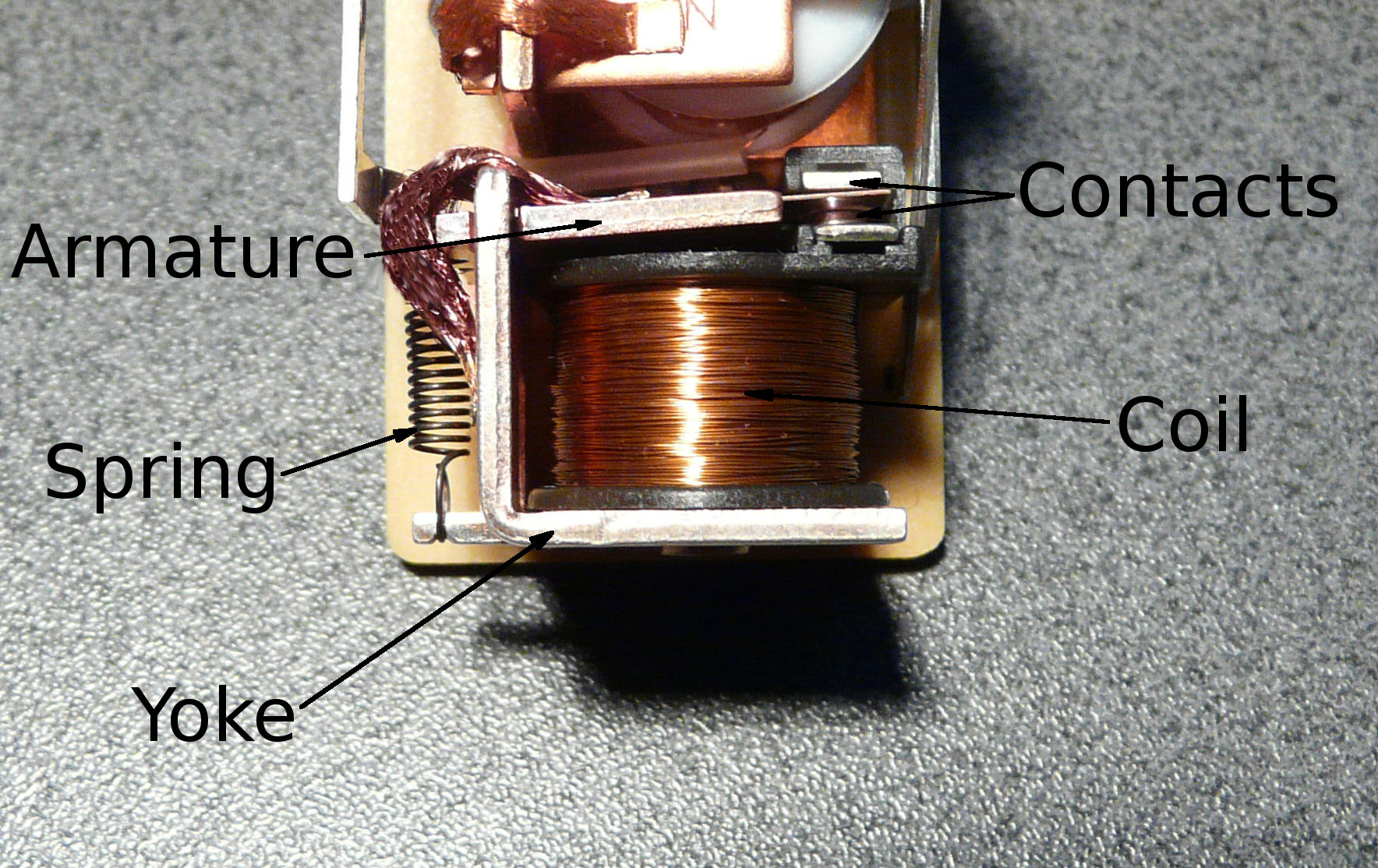
This labeled relay helps identify the coil, armature and contact system that share the package's thermal paths. It is explanatory and is not a dimensional drawing of a QIANJI model. Image: Relay Parts by David Boettcher, released into the public domain via Wikimedia Commons.
Why touch is not an acceptance test
Skin sensation changes with contact time, surface material, airflow and the person making the judgment. It cannot reveal the hottest point inside the winding. Case temperature, terminal temperature and winding temperature are related, but they are not interchangeable values.
An infrared camera is useful for comparing identical positions or finding hot terminals, but shiny surfaces and wrong emissivity settings can mislead it. A thermocouple or resistance-based winding method can provide better evidence when the manufacturer or applicable test procedure defines how to use it. Always record local ambient temperature and the time required to reach a stable condition.
Signs that heat is no longer normal
- browning, deformation, swelling or melting around the coil or case;
- a burnt varnish or plastic odor;
- buzzing, chatter, delayed pickup, dropout or incomplete armature travel;
- unexpected coil-current or resistance change at a known temperature;
- scorched PCB areas, discolored socket terminals or loose connections;
- repeated fuse operation, driver failure or a relay much hotter than comparable units; and
- an intermittent or open coil after a period of abnormal heat.
2. How Coil Voltage, Ambient and Load Heat Add Together
For a DC coil supplied from a stable voltage, a useful first approximation is Pcoil = Vcoil2 / Rcoil. The voltage must be the value at the coil terminals, and the resistance must belong to the relevant winding temperature. The equation explains why overvoltage can raise heat quickly, but it is not a universal field-temperature calculator.
Copper resistance rises as the coil warms. Panasonic's relay-use cautions give about 0.4% per degree Celsius as a general copper relationship. At a fixed DC voltage, a healthy hot coil therefore normally draws less current than it did when cold. Its magnetic force also falls, which is why hot pickup and holding margin matter.
TE Connectivity's DC relay temperature model separates coil self-heating, ambient temperature and heat transferred from the loaded contact system. In simplified form, coil temperature rise depends on coil dissipation multiplied by the relay's coil-to-ambient thermal resistance. That thermal resistance changes with construction, airflow, mounting and the final enclosure.
|
Heat Contributor |
Why It Is Missed |
Evidence to Collect |
|---|---|---|
|
Coil dissipation |
The supply marking is checked, but the actual terminal voltage or ON time is not |
Terminal voltage, current/waveform, coil code and actual duty |
|
Local ambient |
Room temperature is used even though the closed panel contains hot spots |
Air temperature beside the relay at the highest normal system load |
|
Contacts and terminals |
Coil data is reviewed while I2R heat in the power path is ignored |
Load current, voltage drop, conductor/terminal condition and temperature |
|
Packing and airflow |
A spacious bench test does not reproduce the installed thermal path |
Relay spacing, orientation, socket/PCB, door, filter and fan condition |
|
Nearby equipment |
Drives, transformers, resistors and power supplies radiate or conduct heat |
Thermal map and operating sequence of adjacent heat sources |
Calculation boundary: use V2/R to reason about a DC winding only with a stated temperature reference. Do not use cold DC resistance to calculate an AC coil's operating current or heat. AC impedance also depends on inductance, frequency and the magnetic circuit.
3. The Main Reasons Relay Coils Overheat
3.1 Overvoltage or the wrong coil rating
Overvoltage is the most direct electrical cause. It may come from fitting a 12 V coil in a 24 V circuit, selecting the wrong transformer tap, setting a control supply too high, allowing a lightly loaded supply to rise, or confusing similar part numbers. A boost-and-hold driver can also overheat a coil when the starting boost never changes to the intended hold level.
Panasonic states that rated coil voltage should be applied and warns that exceeding the maximum applied voltage can cause temperature rise, winding layer shorts and burnout. OMRON's mechanical PCB relay troubleshooting guide describes the failure loop: excessive heat damages wire coating, adjacent turns short, resistance falls, current rises and even more heat is generated.
Maximum applied voltage is model- and condition-specific. A percentage found in another relay family or contactor manual is not a universal continuous-use allowance.
3.2 Wrong AC/DC type, frequency or waveform
A voltage number does not fully define a coil. A 24 VAC coil and a 24 VDC coil can have different winding resistance, magnetic construction and thermal behavior. TE Connectivity's AC/DC coil application note shows why applying the marked AC voltage as DC can develop far more coil power: the inductive part of AC impedance is no longer limiting current.
Using AC on a DC coil can create inadequate magnetic force, buzzing and repeated contact motion unless the manufacturer provides an approved rectifier/filter method. For an AC coil, 50 Hz and 60 Hz operation may have different current and voltage limits. For a DC coil, excessive ripple or an unsuitable PWM waveform may reduce pickup or holding force even when a handheld meter displays an acceptable average.
3.3 High local ambient and poor heat rejection
The applicable ambient is the air immediately around the installed relay, not the room specification. Closed doors, clogged filters, stopped fans, summer temperature, simultaneous load operation and adjacent power components can create a local hot spot. Tight relay banks and low-airflow enclosures also make it harder for heat to leave.
A published operating-temperature range does not guarantee that every combination of coil voltage, contact current, spacing and mounting is acceptable at the range endpoint. Qualify the finished assembly at maximum normal coil voltage, local ambient and contact load, then preserve the approved layout and airflow through change control.
3.4 Wrong duty: an intermittent or pulse coil held continuously
Many ordinary non-latching relays are intended for continuous coil energization, but this cannot be assumed for every relay, timer, latching coil or special actuator. A pulse coil can be damaged if a PLC fault holds it ON. An intermittent-duty coil can also exceed its thermal limit when the real ON time, cycle rate or recovery time differs from the specified schedule.
Intermittent operation may produce a lower average temperature than continuous operation, but the result depends on the thermal time constant, previous cycles, ambient and mounting. Use the exact duty statement and verify the actual control sequence rather than extrapolating from a nominal wattage.
3.5 The armature does not fully seat
Undervoltage is not simply the opposite of overvoltage. In a basic DC coil, lower voltage normally reduces direct winding power, although it can still cause poor pickup, dropout or chatter. In an AC contactor or AC relay, incomplete pull-in can be much more dangerous because the open magnetic circuit has lower impedance and the coil may remain at a high pull-in current.
Schneider Electric identifies undervoltage, dirt or rust on pole faces, an incorrect coil and mechanical obstruction as causes of an overheated contactor coil. The supply may look normal at the transformer while long control wires, loose contacts, an undersized transformer or simultaneous motor starting create a voltage dip at the coil.
3.6 Damaged turns, corrosion or hot connections
Prior overtemperature, moisture, corrosive contamination, vibration or mechanical damage can weaken winding insulation. Shorted turns reduce effective resistance and can start a self-accelerating current and heat cycle. An open coil may be the final stage, not the first failure event.
Heat marks near a relay do not always begin inside the coil. A loose screw terminal, weak socket clip, poor solder joint, undersized conductor or overloaded contact path can create local I2R heat. Inspect the relay, socket, PCB, conductors and contact load as one thermal system.
|
Likely Cause |
Typical Clues |
Confirmation and Action |
|---|---|---|
|
Overvoltage or wrong coil |
Fast heating, service replacement, supply/tap change, burnt odor |
Measure terminal voltage, verify the complete suffix, correct the supply and replace damaged parts |
|
Wrong AC/DC, frequency or waveform |
Hum, poor pull-in, unexpected current or heating after a driver change |
Verify supply type/frequency/ripple and use only an approved coil-and-driver combination |
|
High ambient or crowded panel |
Problem worsens with door closed or several devices energized |
Measure local ambient and revise spacing, airflow, layout or relay selection |
|
Armature not seated |
AC hum, chatter, voltage dip, dirt or mechanical drag |
Capture voltage during the event, isolate, inspect movement and replace heat-damaged coils/contactors |
|
Shorted turns or insulation damage |
Very abnormal heat, swelling, altered resistance or later open circuit |
Remove and replace the device; investigate prior voltage, heat, contamination or mechanical stress |
|
Socket, terminal or contact heat |
Localized browning, high voltage drop, loose or overloaded connection |
Correct the connection/load/protection and replace every heat-damaged component |
4. DC vs AC Relay Coils: Different Failure Logic
A DC coil's steady current is mainly set by terminal voltage and winding resistance. As copper warms, resistance increases and current falls at a fixed voltage. That lowers magnetic ampere-turns, so a design that barely pulls in when cold may fail after the coil, panel and supply reach worst-case conditions.
An AC coil has resistance plus inductive reactance. Its impedance also changes with frequency and magnetic-circuit position. When the armature seats, the magnetic path reaches its intended low-reluctance condition. If voltage is too low or something blocks travel, an AC coil can stay in its high-current pull-in state, hum and overheat.

The diagram shows the armature away from the coil core and then pulled into its energized position. For an AC relay or contactor, failure to reach the intended seated position can sustain abnormal coil current. Image: Relay principle horizontal by Bisgaard and Teslaton, used unmodified under CC BY-SA 3.0.
|
Question |
DC Coil |
AC Coil |
|---|---|---|
|
What sets operating current? |
Applied voltage and winding resistance |
Voltage, resistance, inductive reactance, frequency and magnetic condition |
|
What can low voltage do? |
Reduce direct power but cause poor pickup, dropout or chatter |
Prevent full seating and prolong high pull-in current |
|
Why is cold resistance insufficient? |
Resistance changes with winding temperature and tolerance |
Cold DC resistance omits inductive and magnetic operating behavior |
|
Can power reduction help? |
Sometimes, after positive pickup and full hold-margin validation |
Only when the exact manufacturer specifies a suitable control method |
Do not reduce coil power casually to make a relay cooler. TE's coil power-reduction guidance notes that hold voltage is often not a controlled data-sheet parameter. Less holding energy can reduce shock and vibration margin or cause dropout at high temperature. Validate the exact relay, driver and finished equipment.
5. A Safe Relay Coil Overheating Test Procedure
Use evidence to separate coil, supply, mechanical, installation and load-side causes. If the device already shows visible thermal damage or creates a safety-critical unexplained condition, stop repeated testing and replace it through the approved process.
- Record the exact identity. Photograph the manufacturer, full part number, coil suffix, rated voltage, AC/DC marking, frequency, socket and wiring before removal.
- Review the exact data sheet. Find nominal voltage, operate/release range, maximum applied voltage conditions, coil power, duty, ambient limits, mounting notes and temperature-rise information.
- Isolate and inspect. Look for melting, discoloration, damaged socket clips, loose terminals, corrosion, contamination, scorched PCB areas and blocked armature movement.
- Measure at the coil terminals. Under an approved live-work method, capture DC voltage/ripple or true-RMS AC voltage/frequency during pickup, hold and the event that causes trouble.
- Verify full mechanical operation. Determine whether the relay pulls in crisply and stays seated. Investigate hum, chatter, delayed pickup and dropout. Inspect pole faces or linkage only after isolation and only where the device is serviceable.
- Measure the thermal context. Record local ambient, coil/case and terminal temperatures, contact load, spacing, orientation, nearby heat sources and door/filter/fan condition.
- Allow stabilization. When safe and appropriate, run the approved configuration until temperatures stop changing significantly. Record the method and time, not just one spot reading.
- Compare and decide. Use exact manufacturer limits and the previously validated configuration. Replace damage only after correcting its supply, mechanical, thermal or load-side cause.
|
Measurement |
Good Practice |
Common Mistake |
|---|---|---|
|
Coil-terminal voltage |
Capture pickup, hold and known supply disturbances at A1/A2 or the coil pins |
Measuring only an unloaded power supply or transformer |
|
Coil current/waveform |
Use a method suitable for DC, AC, PWM or rectified waveforms |
Assuming catalog watts or a meter average proves installed behavior |
|
Temperature |
Use a documented sensor/IR method and record ambient, location and time |
Using touch or comparing unlike surface materials |
|
Cold and hot resistance |
Measure safely at known temperature and interpret with exact coil data |
Declaring failure from one reading without temperature or tolerance |
|
Contact/terminal heat |
Test with the real load and inspect conductor size, connection and voltage drop |
Blaming the coil while a loose or overloaded power terminal heats the package |
Stop condition: do not continue repeated energization when there is melting, swelling, insulation breakdown, arcing at a coil terminal, confirmed shorted turns, strong burnt odor or a safety-critical unexplained failure. Testing should not turn a damaged relay into a fire, shock or unexpected-motion hazard.
6. How to Prevent Relay Coil Overheating in New Designs
Specify the complete coil requirement
Do not purchase only a "24 V relay." Specify AC or DC, frequency, nominal/minimum/maximum terminal voltage, ripple or PWM, continuous/intermittent/latching duty, maximum ON time, operations per hour and local operating temperature. Control the complete coil suffix in the bill of materials and approved-alternate list.
When selecting a PCB-mounted device, review QIANJI's PCB relay range together with the exact coil and contact data. For replaceable control-panel devices, compare the general-purpose relay and compatible relay socket information. High-current applications also need the correct make, carry and break evidence from the selected power relay; contact heat cannot be separated from package temperature by assumption.
Design the control supply for pickup and hold
Size supplies, transformer capacity and conductors for the worst simultaneous coil demand and pickup event, not the holding current of one room-temperature sample. Verify voltage at the farthest coil while motors, valves or other loads start. Include output-device voltage drop, cable length, connector resistance, ripple and tolerance.
If PWM, a series resistor, a coil economizer or boost-and-hold control is used, qualify the entire waveform. Verify positive pickup, full seating, holding force at high temperature and low supply, release time, vibration tolerance, driver stress and EMC. Do not copy a hold duty cycle from another relay family.
Control the installed thermal environment
Keep relays away from braking resistors, transformers, large power supplies and other high-loss components where practical. Follow supplier spacing and orientation instructions. Test with the final PCB or socket, cabinet door closed, normal filter restriction and the intended fan state. Include the highest normal contact current.
Mark coil voltage and AC/DC type on drawings, wiring labels and spares. Key sockets or connectors where a wrong-coil replacement is foreseeable. Treat changes to the relay, socket, control supply, cabinet layout, airflow, load current, cable length or operating temperature as triggers for revalidation.
|
Design Control |
Benefit |
Required Validation |
|---|---|---|
|
Suitable lower-power DC coil |
Reduces continuous coil dissipation |
Pickup, hold and release at supply/temperature extremes plus shock and vibration |
|
Approved power-reduction driver |
Reduces holding energy after reliable pull-in |
Waveform, seating, temperature, timing, EMC and driver stress |
|
Spacing and airflow improvement |
Lowers local ambient and improves heat rejection |
Thermal map with final door, fan, filter, load and adjacent equipment |
|
Controlled part suffix and keying |
Prevents wrong-voltage or wrong-duty replacements |
BOM, drawing, label, receiving inspection and maintenance procedure |
IEC's IEC 61810-1 provides general functional and safety requirements for electromechanical elementary relays. It also states that the end application can add requirements beyond the relay standard. Component compliance does not replace equipment-level thermal, electrical or functional validation.
7. Three Practical Failure Scenarios
A 24 VDC interface relay is hot in a crowded cabinet
The terminal voltage is within the exact relay's stated range and there is no chatter, but the coil is continuously energized. The local air beside the relay is far hotter than the room, nearby power components are operating, and production units have less spacing than the prototype.
The likely cause is normal coil dissipation combined with high local ambient and poor heat rejection. The fix is not a higher-voltage coil. Recheck the continuous-duty and temperature data, improve layout or airflow, consider an approved lower-power family only after pickup/hold testing, and repeat a stabilized thermal test in the finished enclosure.
An AC contactor hums and burns during motor starting
A measurement at the control transformer looks normal, but voltage at the coil terminals dips during a simultaneous motor start. After safe isolation, contamination is also found on the magnetic pole faces. The armature does not seal reliably, so the AC coil stays longer in its high-current pull-in condition.
Correct the control-power drop and mechanical contamination, confirm the exact coil voltage/frequency and verify pickup at the worst event. Replace the thermally damaged coil or contactor rather than assuming that cooling or cleaning restored insulation life.
A replacement relay smells burnt after service
The replacement fits the same socket and has a similar voltage number, but its suffix identifies a different supply type or duty. It operates briefly and then develops abnormal heat. The correct action is to stop energization, verify the source waveform and complete part code, fit the exact approved replacement and improve spare-part identification.
8. Relay Coil Overheating RFQ Checklist
A supplier cannot assess an overheating relay from contact current and nominal coil voltage alone. Provide the following evidence for a replacement, alternate or new design:
- Exact device: manufacturer, full part number, coil suffix, socket/base, drawings and approved alternates;
- Coil supply: AC/DC, nominal/minimum/maximum voltage, terminal readings, frequency, ripple, waveform, polarity and any economizer;
- Duty: continuous or intermittent operation, maximum ON time, operations per hour and command sequence;
- Thermal environment: local ambient, enclosure, airflow, orientation, spacing, nearby heat sources and altitude where relevant;
- Contact load: AC/DC voltage, carry/make/break current, inrush, switching frequency, conductor/terminal arrangement and protection;
- Failure evidence: photos, odor/discoloration, voltage/current logs, temperature method, resistance readings and event history; and
- Compliance needs: target market, equipment standard, safety role, traceability and required validation.
For a QIANJI technical review, send this information through the QIANJI inquiry page. Ask the supplier to confirm permissible coil supply and duty, applicable temperature limits, mounting restrictions, suitable low-power or continuous-duty options, and the tests required in the final assembly.
Frequently Asked Questions
Is it normal for a relay coil to get hot?
Often, yes. A continuously energized non-latching relay produces heat. Acceptance depends on the exact relay's coil voltage, duty, local ambient, mounting, contact load and manufacturer limits. A burnt odor, deformation, chatter or unreliable operation is not normal.
Can low voltage make a relay coil overheat?
It can contribute, but the mechanism differs. Low voltage normally reduces direct power in a basic DC coil, yet it can cause poor pickup, dropout or chatter. In an AC relay or contactor, failure to pull in fully can keep coil impedance low and current high. Measure voltage at the coil terminals during the actual event.
Why is my 24 VDC relay coil hot even at 24 V?
The nominal voltage alone does not prove adequate thermal margin. Continuous duty, high local ambient, tight packing, poor airflow, contact/terminal heat, ripple and mounting can make the installed relay hotter than a bench sample. Compare the complete application with the exact data sheet.
What happens if an AC relay coil is connected to DC?
Do not assume equal numeric voltage is safe. An AC coil relies partly on inductive impedance. Applying its marked AC voltage as DC can cause much higher current and power, overheat the winding and create shorted turns. Use only a manufacturer-approved conversion method and voltage for that exact part.
Why does a relay or contactor buzz and get hot?
Buzzing often means the armature is not fully seated or is repeatedly moving. Causes include low terminal voltage, supply dips, wrong frequency, the wrong coil, dirty or rusty pole faces, a broken shading element or mechanical obstruction. Isolate safely before inspecting mechanical parts.
Can high contact current heat the coil?
Yes. Contact, terminal, conductor and PCB losses can transfer heat into the relay package. The amount is model- and installation-specific. Verify load current, terminal voltage drop, conductor size, connection condition and temperature under the real load.
Will PWM or a coil economizer prevent overheating?
It may reduce DC holding power after reliable pickup, but it is not a universal repair. Too much reduction can lower magnetic holding force and increase sensitivity to high temperature, supply variation, shock or vibration. Validate pickup, hold, release, temperature, waveform and EMC with the exact relay.
Does a flyback diode keep a DC relay coil cooler?
A flyback diode mainly clamps the turn-off transient and slows current decay after de-energization. It does not normally reduce the coil's steady energized power. It can also lengthen release time and alter contact dynamics, so choose suppression for the driver, relay and load requirements.
Should a relay with a burnt coil be reused after cooling?
No. Replace a relay with swelling, melting, burnt odor, confirmed shorted turns, insulation damage or unexplained abnormal heat. Cooling does not restore damaged enamel or bobbin material. Correct the supply, duty, mechanical, connection or ambient cause before energizing the replacement.
Final Recommendation
Do not diagnose relay coil overheating by touch or by nominal voltage alone. Prove the full coil identity and measure the actual terminal supply first. Then investigate duty, local ambient, packing, contact/terminal heat and complete armature seating. Separate DC-coil and AC-coil failure logic, because undervoltage and resistance measurements do not mean the same thing in both systems.
For a new design, treat the coil as a power-consuming component with defined voltage type, frequency, waveform, duty, local ambient and mounting. Validate the final panel or equipment at worst normal supply, temperature and contact load. That evidence is more reliable than any universal percentage or temperature rule.
Technical References
- TE Connectivity: Temperature Considerations for DC Relays
- TE Connectivity: Coil Voltage and Temperature Compensation
- TE Connectivity: Proper Coil Drive Is Critical to Good Relay/Contactor Performance
- TE Connectivity: Operating DC Relays from AC and Vice-Versa
- TE Connectivity: DC Relay Coil Power Reduction Options
- Panasonic Industry: Relays Cautions for Use
- OMRON: Troubleshooting Case Studies, Mechanical PCB Relay Edition
- Schneider Electric: Model 6 MCC Troubleshooting
- IEC 61810-1: Electromechanical Elementary Relays - General and Safety Requirements
This article provides general engineering guidance. Final component approval depends on the exact relay documentation, installed conditions, equipment standard and the organization's safety and validation process.