


Short answer: for an ordinary motor that starts and stops occasionally, use a properly rated contactor or motor starter selected for the motor duty-not a general-purpose SSR simply because its current rating looks large enough. For a resistive heater that cycles frequently under temperature control, a correctly selected SSR is often the better normal control switch, provided its heat sink, derating, protection and independent over-temperature shutdown are engineered as part of the system.
A mechanical relay can still be the right choice for modest loads, low switching frequency, low on-state loss and a true physical contact gap. An SSR is attractive when silent, rapid and frequent switching matters. The correct choice depends on the load waveform, switching frequency, failure consequence, thermal environment and required isolation-not only on rated amperes.
Important boundary: this guide supports product selection and design review; it does not replace the selected device's datasheet, applicable electrical standards, machine risk assessment or validation under the real load.
Mechanical Relay vs SSR: Quick Decision Table
|
Application |
Normal Starting Point |
Main Reason |
|---|---|---|
|
Across-the-line AC motor, occasional starts |
Contactor or motor starter |
Designed and rated for motor starting, running and interruption duty. |
|
Motor requiring soft start, reduced stress or frequent electronic control |
Dedicated semiconductor motor controller, soft starter or drive |
Motor-specific ratings, control functions and protection coordination are required. |
|
Resistance heater under fast time-proportioning control |
Zero-cross AC SSR, when compatible with the load |
No contact wear and suitable for frequent switching, but thermal design is mandatory. |
|
Heater switched only a few times per day |
Mechanical relay or contactor |
Low switching frequency may not justify continuous SSR heat loss. |
|
Maintenance isolation or lockout point |
Approved mechanical isolating device |
SSR off-state leakage means "control off" is not the same as physical isolation. |
The table is a starting point, not a substitute for coordination. A heater panel may use an SSR for routine temperature control and a contactor for independent power removal. A motor system may use a semiconductor controller together with a series mechanical switching device. In other words, the strongest design is often a coordinated architecture rather than one switching technology used for every purpose.
First, Separate Four Different Devices
The phrase "mechanical relay versus SSR" can hide an important classification problem. Four devices may all receive a small control signal and switch a larger load, but they are not interchangeable.
|
Device |
What It Is Best At |
Selection Warning |
|---|---|---|
|
General-purpose electromechanical relay |
Control panels, interface duties and moderate switching with physical contacts. |
A resistive current rating does not automatically qualify it for a motor. |
|
Contactor or motor starter |
Repeated switching of motors and other power loads under defined utilization categories. |
A starter normally combines switching with overload protection; a contactor alone does not provide every protective function. |
|
General-purpose SSR |
Silent, frequent switching of compatible AC or DC loads. |
It produces heat while on, leaks current while off and may fail short. |
|
Semiconductor motor controller, soft starter or drive |
Motor-specific electronic starting, stopping, torque or speed control. |
Use the exact product's motor ratings and protection requirements; do not substitute a generic heater SSR. |
This separation is reflected in the IEC 60947 family. IEC 60947-4-1 covers electromechanical contactors and motor starters. IEC 60947-4-2 addresses semiconductor motor controllers, starters and soft starters. IEC 60947-4-3 addresses semiconductor controllers and contactors for non-motor AC loads. The distinction matters because a device tested for one type of duty should not be assumed suitable for another.
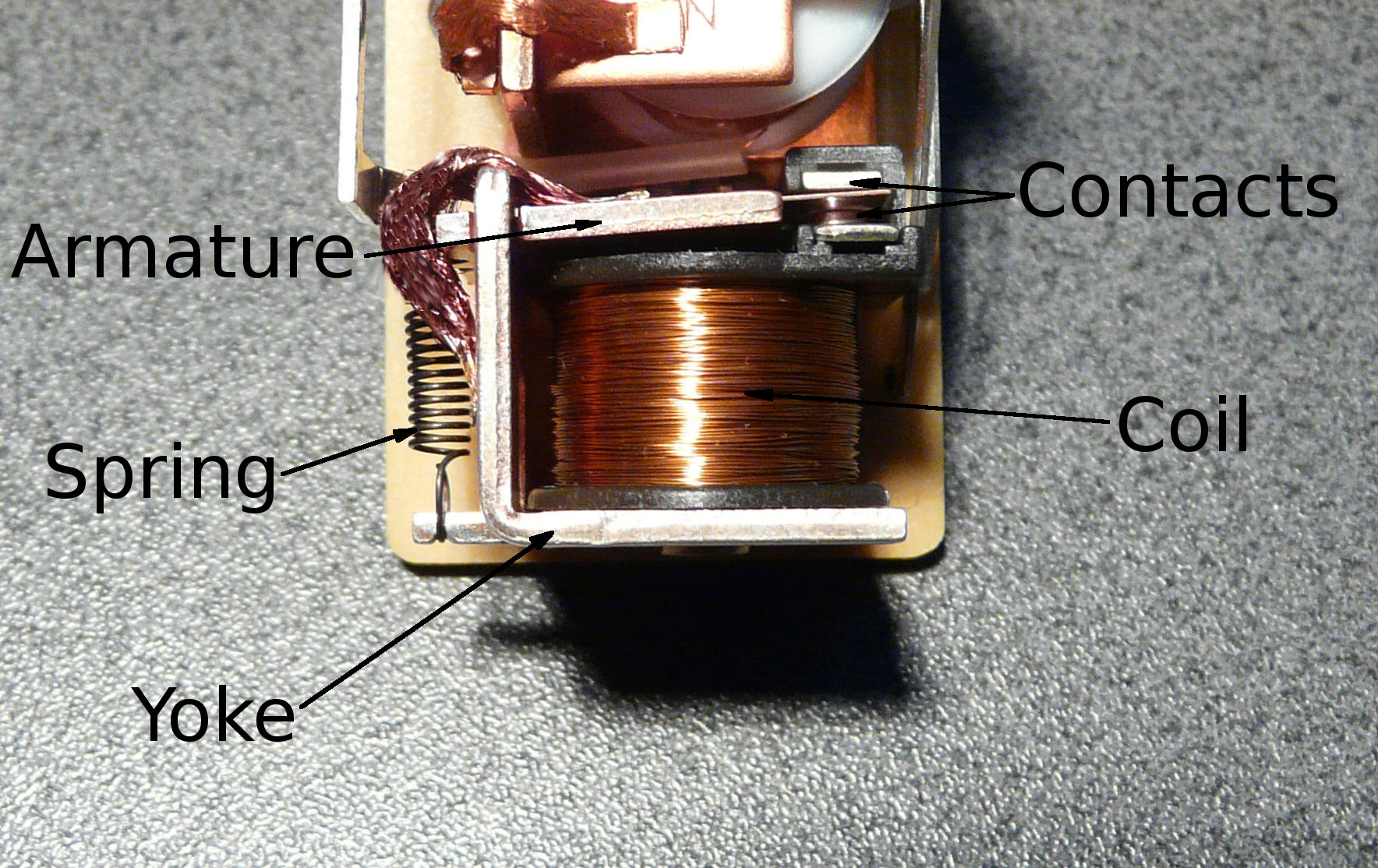
Image: Relay Parts by David Boettcher, released into the public domain via Wikimedia Commons.
A mechanical relay energizes a coil, moves an armature and changes the state of physical contacts. The closed contacts usually have low voltage drop, and the open contacts provide a visible physical separation inside the device. However, every loaded opening and closing event can produce bounce, arcing, erosion or welding.
An SSR uses semiconductor switching elements rather than moving contacts. It can switch quickly and silently without contact bounce, but its output is not an ideal open or closed switch. The on-state voltage drop creates heat, and the off-state circuit normally allows some leakage current.
Core Differences That Affect Real Equipment
|
Design Factor |
Mechanical Relay or Contactor |
Solid State Relay |
|---|---|---|
|
Switching element |
Moving metal contacts. |
Triac, thyristor, MOSFET or another semiconductor arrangement. |
|
Wear mechanism |
Electrical and mechanical wear increases with switching stress. |
No contact wear, but semiconductor aging and thermal damage remain possible. |
|
On-state behavior |
Usually low contact voltage drop; coil consumes power. |
Output voltage drop or resistance produces continuous heat. |
|
Off-state behavior |
Physical contact gap, subject to the device's insulation ratings. |
Leakage current remains; output must not be treated as isolation. |
|
Switching frequency |
Limited by mechanical response and electrical endurance. |
Well suited to frequent control when thermal limits are respected. |
|
Failure tendency |
May fail open, fail to operate or weld closed. |
May fail open, but shorted output is an important design case. |
Neither technology is universally more reliable. Reliability depends on whether the device operates inside its electrical, thermal, mechanical and environmental limits. A lightly loaded contactor that starts a motor twice per day may be a robust solution. A general-purpose relay asked to switch a motor every few seconds may not be. A well-cooled SSR controlling a resistance heater may deliver very high cycle capability, while an oversized-looking SSR on an inadequate heat sink can fail quickly.
Why Motors Usually Point to a Contactor or Motor Starter
A motor is not a simple steady-current load. When an induction motor starts, it can draw several times its normal running current. The switching device must make that inrush repeatedly, carry running current, interrupt the appropriate current and survive the required starts per hour. A motor starter must also coordinate switching with overload and short-circuit protection.
Utilization categories help prevent a common selection error. Schneider Electric's official explanation describes AC-1 as mainly non-inductive or slightly inductive loads and AC-3 as squirrel-cage motor duty. It notes that an AC-3 contactor makes the motor inrush current and breaks the running current. Therefore, a contactor's AC-1 ampere rating for a heater cannot be copied directly into an AC-3 motor application.
For ordinary direct-on-line motor control, begin with the motor nameplate and the manufacturer's motor-duty selection table. Confirm:
1. Motor voltage, phase, frequency and full-load current.
2. Motor power and starting method.
3. Required utilization category and switching frequency.
4. Starts per hour, acceleration time, jogging or plugging duty.
5. Ambient temperature, enclosure temperature and installation altitude.
6. Overload relay, fuse or circuit-breaker coordination and fault level.
7. Required auxiliary contacts, coil voltage, control logic and safety functions.
A general-purpose mechanical relay may operate a contactor coil or switch a small, specifically rated motor. It should not be promoted to a motor power device solely because its contact rating is numerically above the motor's full-load current.
Can an SSR Control a Motor?
Yes-but only when the exact SSR or semiconductor controller is specified for that motor application. "SSR" is a broad product class, not a motor-duty approval.
A motor can impose starting inrush, inductive turn-off stress, phase imbalance and abnormal stalled-current conditions. A three-phase motor also requires coordinated switching of its phases. A generic single-phase, zero-cross heater SSR may have neither the motor rating nor the protective behavior needed for the application.
Use a dedicated semiconductor motor controller, solid-state contactor, soft starter or variable-frequency drive when the application needs benefits such as:
Frequent electronic starting and stopping. Confirm the manufacturer's permitted starts per hour and thermal duty.
Reduced mechanical shock. A soft starter can manage acceleration and, in some products, deceleration.
Speed control. This normally points to a drive, not a basic on/off SSR.
Silent operation. The semiconductor solution still needs correct heat dissipation and protective coordination.
Bypass operation. Some architectures use semiconductor devices for starting and a mechanical bypass contactor after the motor reaches speed, reducing continuous semiconductor losses.
Review the exact product documentation for motor power, current, utilization category, overload class, short-circuit coordination, maximum operating rate and required series mechanical device. If those data are absent, do not infer suitability from a resistive-load current rating.
Why Frequently Cycled Heaters Often Favor SSRs
Resistance heaters are a more natural application for general-purpose AC SSRs, especially when a PID or temperature controller uses short time-proportioning cycles. A mechanical relay or contactor consumes part of its electrical endurance every time it switches. An SSR has no contacts to bounce or erode, so it can accept much faster control cycles when correctly cooled.
For a compatible AC resistance heater, a zero-cross SSR normally turns on when the supply voltage is close to zero. OMRON's official SSR guidance explains that zero-cross switching suppresses noise generated when load current rises suddenly. Watlow also reports that fast-cycle SSR control can improve temperature control and reduce heater thermal cycling compared with slower electromechanical switching.
However, "heater" does not always mean "pure resistance at constant current." Measure or obtain the real cold and hot electrical behavior. Metal heating elements can have a lower cold resistance than their hot resistance. Infrared lamps, tungsten elements, transformers and other heater systems may have substantial inrush or require a different power controller. A zero-cross SSR is not automatically the correct choice for every heating technology.
|
Heater Duty |
Likely Direction |
Verify Before Selection |
|---|---|---|
|
Stable resistance heater, frequent PID time-proportioning |
Zero-cross AC SSR |
Voltage, hot and cold current, cycle period, heat sink and ambient. |
|
Simple heater, only occasional on/off control |
Mechanical relay or contactor may be efficient |
Contact utilization rating, temperature, endurance and switching rate. |
|
High cold-current element or infrared lamp |
Application-specific SSR or power controller |
Inrush waveform, I2t, surge rating and control method. |
|
Transformer-fed heater |
Application-specific controller |
Transformer magnetizing inrush, firing mode and protective coordination. |
SSR Thermal Design: The Rating on the Case Is Not the Panel Rating
An SSR creates heat whenever load current flows. For a device characterized by an on-state voltage drop, a first screening estimate is:
Approximate SSR conduction loss = on-state voltage drop × RMS load current.
For a MOSFET output characterized by on-resistance, a first screening estimate may use:
Approximate conduction loss = I2 × Ron.
These equations are not final design rules. The manufacturer's datasheet may specify a more appropriate method, switching losses, thermal impedance, derating curves and maximum junction or case temperatures. Use those values for the exact model.
Suppose an AC SSR has a representative on-state drop of 1.5 V and carries 20 A RMS. The screening loss is about 30 W. That heat must travel from the semiconductor junction through the package and interface material into a heat sink, and then into the surrounding air. A small enclosure at high ambient temperature can make the same SSR run far hotter than it would on an open laboratory bench.

Image: Solid-state relay with heat sink by Relequick relays, licensed under CC BY-SA 4.0 via Wikimedia Commons. No changes made.
OMRON's official technical information states that SSR models without built-in heat sinks require an appropriate external heat sink and that thermal grease or a specified conductive sheet is needed to transfer heat effectively. Its guidance also illustrates why load-current capacity falls as ambient temperature rises. Therefore, a responsible SSR selection must confirm:
1. Actual RMS current and load waveform.
2. Maximum enclosure ambient, not only room temperature.
3. Required heat-sink thermal resistance and mounting orientation.
4. Thermal interface material, flatness, fastener torque and mounting pressure.
5. Airflow, spacing from neighboring heat sources and wiring temperature rating.
6. Manufacturer derating curve and permitted case temperature.
7. Panel behavior after a fan failure or elevated seasonal ambient.
The QIANJI solid state relay category can help buyers identify an appropriate product family. Final selection still requires the exact model's output type, voltage range, control input, current derating, heat-sink requirement and load compatibility.
Off-State Leakage, Isolation and Failure Mode
An SSR that receives an "off" command is not the same as an open mechanical contact. Internal output networks and semiconductor devices allow a small leakage current. Depending on the load and measurement instrument, this can produce a noticeable voltage at the output, a faint lamp glow or an unexpected input state.
Never use an SSR as the only maintenance isolation point. De-energize the circuit with an approved isolating device, apply the required lockout/tagout procedure and verify absence of voltage using the method required for the installation.
A shorted SSR must also be included in the risk analysis. Watlow's official SSR literature identifies shorted output as a key failure concern and states that a shorted-SSR alarm is not a substitute for an approved high-temperature limit device. Where uncontrolled heater power could create fire, product damage or a personnel hazard, the system should have an independent means to detect the abnormal condition and remove power.
A robust heater architecture commonly separates these functions:
|
Function |
Typical Device |
Design Question |
|---|---|---|
|
Normal temperature control |
PID controller plus SSR |
Can it regulate the process at the required cycle rate? |
|
Independent over-temperature limit |
Separate limit controller and sensor where required |
Does it detect a dangerous temperature independently of the normal control loop? |
|
Power removal after a limit trip |
Properly rated contactor or other approved disconnecting means |
Will it interrupt all required live conductors and require the correct reset action? |
|
Short-circuit and semiconductor protection |
Coordinated fuse or protective device |
Does the protection match the available fault current and manufacturer's coordination data? |
|
Maintenance isolation |
Approved isolator or disconnect |
Can authorized personnel lock, tag and verify the circuit safely? |
Exact requirements depend on the machine, jurisdiction and applicable standard. The key principle is that a single normal-control output should not be assumed to provide regulation, over-temperature protection, fault interruption and maintenance isolation at the same time.
Protection Requirements Are Different
Mechanical contacts and semiconductor outputs respond differently to overloads and transients. A mechanical device may tolerate a brief current peak yet suffer cumulative contact damage. A semiconductor device can be damaged by a short pulse that exceeds its surge energy or junction-temperature limit even if the average current seems modest.
For a mechanical relay or contactor, examine:
Making current and breaking current. The most severe stress may occur at a different point in the cycle.
Utilization category and electrical endurance. Do not replace these with a maximum resistive ampere value.
Arc suppression. An RC network, diode, varistor or another method may reduce stress, but it can also change release time or leakage behavior. Match it to AC/DC duty and the load.
Overload and short-circuit coordination. Confirm the complete assembly, not only the switching component.
For an SSR, examine:
Repetitive and non-repetitive surge ratings. Check peak magnitude, duration and repetition rather than relying on steady current.
Overvoltage protection. Inductive loads and supply transients may require a manufacturer-approved snubber or suppression device.
Fast-acting semiconductor protection. An ordinary branch fuse may protect wiring without protecting the semiconductor. Use the manufacturer's coordination information.
Thermal protection. Fuse protection does not correct an undersized heat sink, obstructed airflow or excessive enclosure ambient.
Selection Workflow for a Motor
Step 1: Define the Motor and Mechanical Duty
Record motor voltage, phase, full-load current, power, efficiency class, starting method, acceleration time and load inertia. Note whether the machine starts under load and whether the sequence includes jogging, reversing, plugging or frequent starts.
Step 2: Choose the Correct Device Class
For basic on/off duty, start with a contactor or motor starter. For soft starting, frequent electronic operation or speed control, evaluate a motor-rated semiconductor controller, soft starter or drive. A control relay may operate the power device's coil, but should not automatically carry the motor power circuit.
Step 3: Apply Motor-Duty Ratings
Use the manufacturer's motor table or utilization-category data for the exact voltage and duty. Do not size from the heater or resistive-load rating. Check starts per hour and any special duty that produces more severe making or breaking stress.
Step 4: Coordinate Protection and Control
Select overload protection, short-circuit protection, disconnecting means, control voltage and auxiliary contacts. Confirm reset behavior after a trip and the machine's required stop category or safety architecture.
Step 5: Validate the Complete Panel
Verify conductor sizing, terminal temperature, enclosure temperature, fault level, clearances and the actual start waveform. Test abnormal states such as a stalled motor, lost phase, welded contact or failed semiconductor output according to the risk assessment.
Selection Workflow for a Heater
Step 1: Define the Electrical Load
Record supply voltage, phase, total heater power, hot current, cold current and element type. Measure the waveform if the heater includes a transformer, lamp-like element or unusual control electronics.
Step 2: Define the Control Method
Confirm simple on/off, time-proportioning, burst firing or phase-angle control. Match the output to the controller signal and required cycle time. A zero-cross SSR is often appropriate for compatible resistance loads; it is not a universal answer for every heater.
Step 3: Complete the Thermal Calculation
Estimate semiconductor loss, then use the exact datasheet's thermal and derating data. Select the heat sink and interface material for the maximum internal ambient. Check orientation, airflow, neighboring heat sources and wiring temperature.
Step 4: Engineer Protection and Independent Shutdown
Coordinate short-circuit and surge protection. Where overheating can create a hazard or costly loss, provide an independent high-limit path and a correctly rated mechanical means of removing power.
Step 5: Test Normal and Fault Conditions
Measure current and case or heat-sink temperature after the panel reaches thermal equilibrium. Confirm correct behavior for a broken sensor, welded contact, shorted SSR, controller output stuck on, blocked ventilation and loss of one supply phase where relevant.
Three Practical Application Examples
Example 1: 3 kW Conveyor Motor
The motor starts 20 times per shift and runs for several minutes between starts. The best starting point is an AC motor starter selected from the manufacturer's motor-duty table, with coordinated overload and short-circuit protection. A general-purpose relay can interface between the PLC and starter coil if its coil-load rating is suitable. A heater-rated SSR is not selected from its printed ampere value.
Example 2: 2 kW Band Heater Controlled by PID
The controller uses a short time-proportioning cycle to hold a tight process temperature. A compatible zero-cross AC SSR can avoid rapid contact wear. The engineer calculates current from the actual supply and heater power, checks cold current, selects a heat sink from the SSR derating data and verifies temperature inside the enclosure. A separate limit controller and contactor remove power if the process exceeds the safe temperature.
Example 3: High-Inrush Heating Element
The heater's cold current is much higher than its steady hot current, and field SSRs have been failing during startup. Increasing the SSR's printed current rating without measuring the waveform may not solve the problem. The team should capture peak current and duration, identify the element type, compare the pulse with the manufacturer's surge and I2t data, review the firing method and confirm the protective-device coordination. An application-specific power controller may be more appropriate.
Troubleshooting Mechanical Relays and SSRs
|
Symptom |
Likely Checks |
Useful Evidence |
|---|---|---|
|
Mechanical relay contacts weld |
Inrush, incorrect load rating, contact bounce, short circuit or excessive switching rate. |
Closing-current waveform, load type, exact datasheet and event counter. |
|
Contactor chatters |
Low coil voltage, unstable control supply, loose wiring or mechanical damage. |
Coil voltage during pickup and hold, control waveform and terminal inspection. |
|
SSR overheats |
Undersized heat sink, poor thermal interface, high ambient, overload or blocked airflow. |
RMS current, case temperature, internal ambient, mounting details and derating curve. |
|
Load remains energized after SSR input turns off |
Shorted SSR, wiring error, control signal still present or unsuitable test method. |
Input voltage, load current, output voltage under load and isolation test after safe shutdown. |
|
Small load flickers or never fully turns off |
SSR leakage current or internal snubber current. |
Datasheet leakage limit, actual load current and manufacturer-approved bleed solution. |
|
Motor does not start reliably through electronic switch |
Wrong device class, insufficient surge capability, voltage drop, phase problem or protection trip. |
Motor start waveform, phase voltages, controller fault history and motor-duty rating. |
Do not troubleshoot energized power equipment beyond the procedures and qualifications permitted for the site. Measurements around mains and motor circuits can expose personnel and instruments to hazardous voltage, arc flash and stored energy.
What to Send a Relay or SSR Supplier
A current value by itself is not enough for a dependable recommendation. A useful request for quotation should include:
Load: motor, resistance heater, lamp, transformer, solenoid or another clearly described load.
Supply: AC or DC, voltage range, phase and frequency.
Current: steady RMS current, measured inrush or starting current, pulse duration and repetition.
Control: input voltage or current, controller output type, required switching frequency and default state.
Installation: panel or PCB mounting, enclosure temperature, ventilation, altitude, vibration and available space.
Protection: available fault current, upstream fuse or breaker, suppression and required coordination.
Compliance: required approvals, applicable equipment standard, insulation level and environmental restrictions.
Failure consequence: what happens if the output fails open, fails to switch or remains on.
For mechanical options, review the QIANJI general-purpose relay range and QIANJI power relay range. For electronic switching, review the QIANJI solid state relay range. Always request confirmation for the exact motor or heater duty rather than selecting only from the category name.
Frequently Asked Questions
Is an SSR always better than a mechanical relay for a heater?
No. An SSR is often better for a compatible resistance heater that switches frequently, but it adds heat loss, off-state leakage and a possible shorted-output failure. A mechanical relay or contactor may be efficient and economical when switching is infrequent. The heater type, cycle rate, thermal design and shutdown architecture decide the answer.
Can I choose an SSR with the same ampere rating as my contactor?
No. The ratings are based on different devices, loads and thermal conditions. An SSR's permitted current depends strongly on heat sink, ambient temperature and load waveform. A contactor also has utilization-category ratings such as AC-1 and AC-3. Compare the complete application with the exact datasheets.
Does a larger SSR eliminate the need for a heat sink?
Not automatically. A larger current rating may reduce stress, but the output still creates conduction loss. Use the exact model's load-current versus ambient curve and heat-sink instructions. Verify temperature after the enclosure reaches steady state.
Does zero-cross switching make any SSR suitable for a motor?
No. Zero-cross describes turn-on behavior near the AC voltage zero point. It does not supply a motor utilization rating, overload protection, phase-loss behavior or short-circuit coordination. Use a motor-rated semiconductor controller or another device specifically approved for the duty.
Can an SSR provide electrical isolation when it is off?
It may provide control-to-output galvanic isolation according to its specifications, but the output terminals still have off-state leakage and do not create a mechanical contact gap. Do not use the off command as maintenance isolation.
Why does my meter show voltage after the SSR is turned off?
A high-impedance meter can display voltage caused by the SSR's leakage current or internal suppression network. Evaluate the output with the manufacturer's recommended test method and a representative load. Treat the circuit as energized until it has been isolated and verified safe.
What is the best relay for a PID-controlled heater?
A zero-cross AC SSR is a common starting point for a compatible resistive heater and time-proportioning PID output. The final choice must match supply, current waveform, control input, cycle time, heat sink, ambient, protective devices and independent over-temperature strategy.
Should a motor use a relay, contactor, soft starter or VFD?
Use a contactor or motor starter for basic on/off control, a soft starter when controlled acceleration or reduced starting stress is needed, and a variable-frequency drive when speed control is required. A small relay may still serve an interface or auxiliary function. Exact selection depends on the motor, machine duty and applicable standards.
Final Recommendation
Choose by load duty, not by the largest ampere number printed on the device.
For motors: begin with a contactor or motor starter rated for the motor utilization duty. Move to a dedicated semiconductor motor controller, soft starter or drive when the application needs electronic starting, frequent operation or speed control.
For heaters: use an SSR when frequent switching and tight temperature control create real value, but design the heat sink, current derating, short-circuit protection, leakage behavior and shorted-output response at the same time. Keep normal control, independent over-temperature protection and maintenance isolation as separate engineering functions.
If you are comparing relay technologies for a new machine or replacing a failed field device, send QIANJI the load waveform, voltage, current, switching rate, enclosure temperature and protection details. Contact QIANJI for model-level selection support and a quotation.
Technical References
IEC 60947-4-1:2023-Electromechanical contactors and motor-starters
IEC 60947-4-2:2020-Semiconductor motor controllers, starters and soft-starters
IEC 60947-4-3:2020-Semiconductor controllers and contactors for non-motor loads
Schneider Electric-AC-1 and AC-3 utilization categories
OMRON-Further information for solid-state relays