

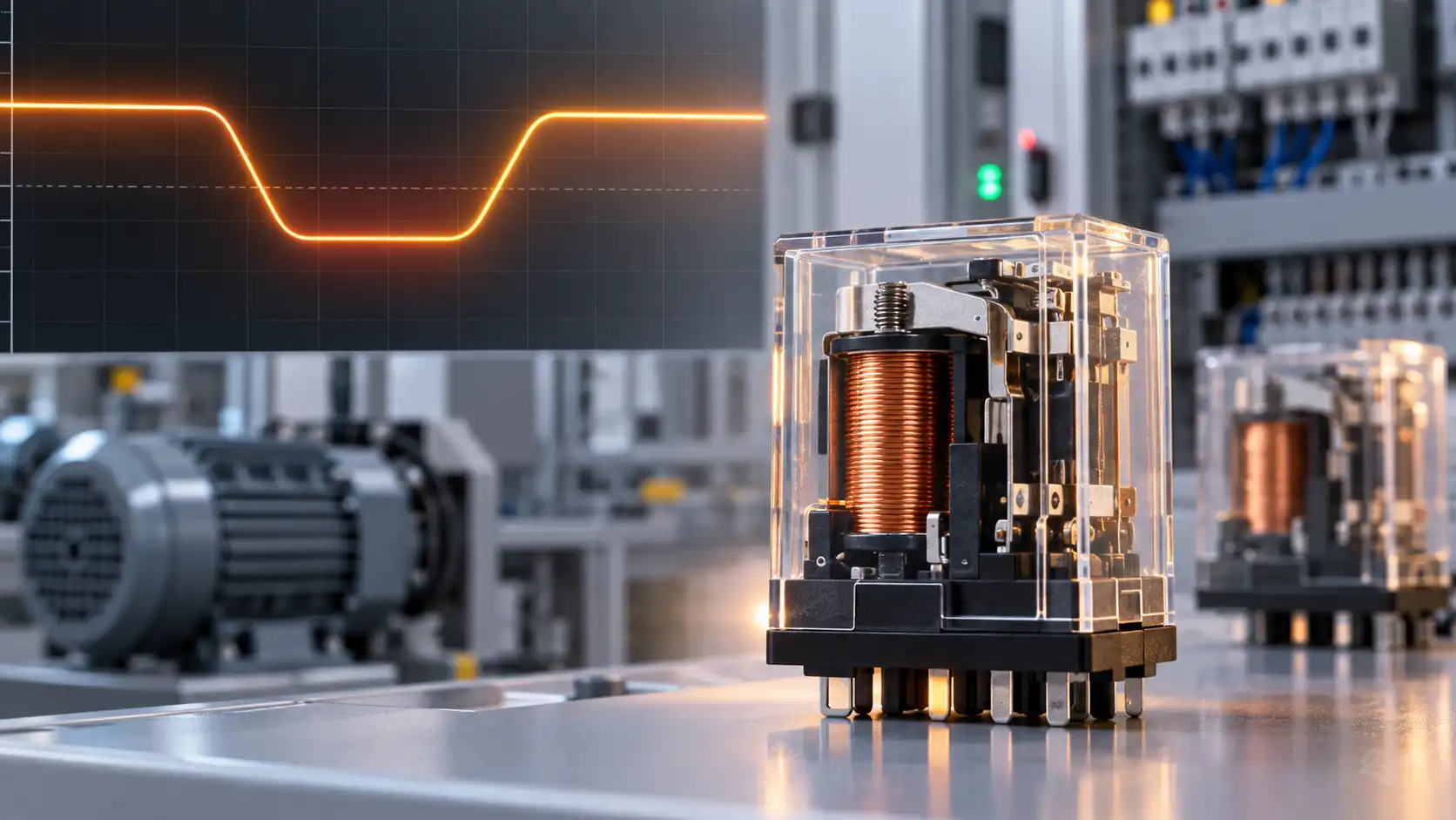
A voltage dip can make a relay stay closed, release, chatter or fail to pick up.
The outcome depends on voltage at the coil terminals, dip duration, temperature, coil drive and whether the armature was already seated. Reliable design must define both the required behavior during undervoltage and the permitted restart after power recovers.
A relay that works on a bench may click repeatedly when a motor starts, drop out inside a hot panel, or refuse to restart after a brief supply disturbance. Replacing it with another relay of the same nominal coil voltage may leave the cause unchanged. For OEM engineers and panel builders, the useful question is not just "How low can the voltage go?" It is "What happens to the contacts throughout the disturbance, and is that acceptable for this machine?"
In this guide, a voltage dip means a temporary reduction in supply voltage, while brownout describes a sustained or recurring undervoltage condition. The word brownout alone does not define a test duration or severity. Record the actual waveform instead. Also separate a supply disturbance from a voltage drop in the coil wiring or a voltage drop across damaged load contacts.
What can a voltage dip make the relay do?
For an ordinary non-latching relay, the state immediately before the dip matters. A relay that is already fully operated may remain held at a voltage that cannot pull in an initially released relay. Neither behavior should be assumed from the nominal voltage printed on the case.
| Observed behavior | What may be happening | Required evidence |
|---|---|---|
| Remains operated | Coil current and stored energy keep the armature seated. | No unacceptable contact interruption at the worst dip, temperature and load. |
| Releases once | Magnetic holding force falls below the return force. | Release occurs within the allowed time and recovery does not cause an unwanted restart. |
| Chatters or repeatedly cycles | The drive, supply or control logic repeatedly crosses an operating boundary. | Synchronized coil-voltage, command, contact and load-current traces. |
| Does not pick up | Available coil drive cannot complete pull-in, especially during a hot restart. | Adequate pickup voltage and duration at the actual coil terminals. |
"Released" describes the armature state, not necessarily a disconnected load. A normally closed contact closes when a healthy non-latching relay releases. A welded contact may fail to open at all. Evaluate the particular contact path and the required machine state.
Why are pickup, holding and dropout voltage different?
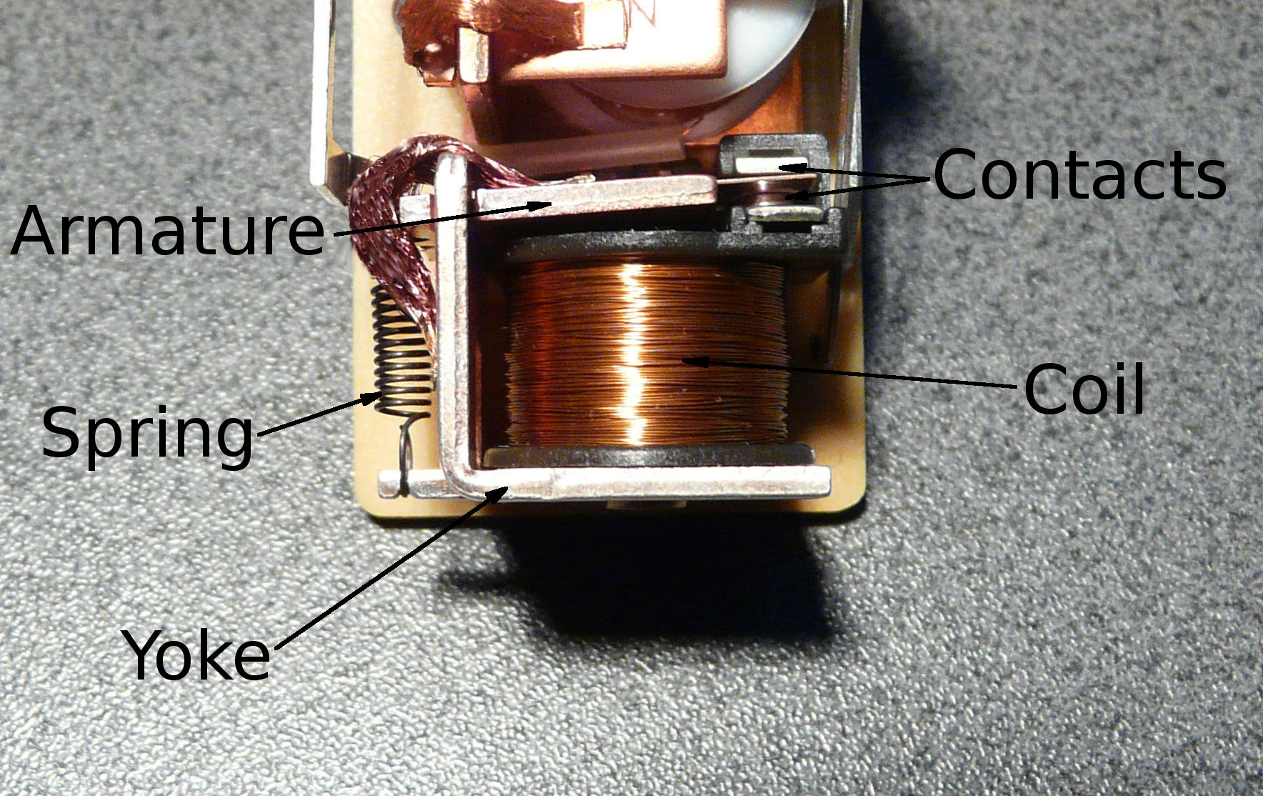
To pick up, the armature must move across its initial air gap against the return spring. Once seated, the magnetic circuit has a smaller gap and generally needs less excitation to remain operated. This explains why a reduced voltage can hold one relay after pickup yet fail to start the same relay from rest.
Read the exact datasheet wording, including maximum, minimum, coil temperature and test conditions. A must-operate limit bounds the pickup threshold. A must-release limit bounds the release threshold. A guaranteed holding voltage, when actually specified, answers a different question: whether the armature remains fully seated after pickup. The detailed terminology is covered in QIANJI's relay pick-up voltage versus drop-out voltage guide.
A 24 VDC example: do not mistake a release limit for a holding guarantee
OMRON's G2R-S DC coil specifications list must-operate voltage as 70% maximum and must-release voltage as 15% minimum, with operating characteristics measured at 23°C coil temperature.
- 24 V × 70% = 16.8 V: the upper limit of the pickup threshold under the specified test conditions.
- 24 V × 15% = 3.6 V: the lower limit of the actual dropout threshold in the falling-voltage test. A specimen can release at a higher voltage.
This does not guarantee that the relay will hold down to 3.6 V, or that 16.8 V is an acceptable continuous drive in a hot enclosure. These figures illustrate one manufacturer's specification; they are not QIANJI ratings or universal relay limits.
How do dip duration and voltage recovery change the result?
A coil has inductance, magnetic flux takes time to decay, and the armature has mechanical inertia. A short interruption may end before the contacts transfer. A shallower but longer dip may allow the armature to release. The response also changes if the dip begins while the armature is moving instead of already seated.
A published maximum release time is not a guaranteed ride-through time. For example, "release time: 10 ms maximum" means the specified release process completes within that limit under its stated test conditions. It does not mean the contacts are guaranteed to remain closed for every interruption shorter than 10 ms. Some specimens may release much earlier.
Recovery deserves its own test. A supply that rises slowly, enters current limiting or repeatedly restarts can leave a relay near its operating boundary. If the relay has released, the recovered supply must support a fresh pull-in, not merely the lower drive that previously held it.
Illustrative shared-supply failure sequence
- The relay closes and a motor or other high-inrush load starts.
- The shared supply voltage falls enough for the relay to release.
- The load disconnects, allowing the supply voltage to recover.
- The relay picks up again and reconnects the starting load, repeating the cycle.
This is an engineering scenario, not a reported customer test. It shows why the first dip may come from the supply, while later dips are reinforced by the relay and load. A larger contact rating alone will not correct this feedback loop.
Can relay chatter damage the contacts even if the load keeps running?
Yes. Repeated opening and closing can interrupt current, create arcs and reconnect inrush loads many times during one disturbance. OMRON identifies contact chatter with continuing arcing as a cause of abnormal relay heating. The amount of damage depends on the load waveform, switching frequency and contact design; a brownout does not automatically mean a relay is ruined.
Distinguish this from contact bounce, the brief mechanical rebound associated with an individual transition. Sustained chatter means the relay is not maintaining its intended state. QIANJI's guide to relay contact bounce and its reduction explains the separate switching phenomenon.
Filtering a PLC feedback input may hide repeated transitions from software, but it cannot stop the power contacts from arcing. Likewise, a coil LED or audible click is not proof of a stable load connection. Verify the contact voltage or load current, and investigate abnormal heating, increased voltage drop or failure to open before returning damaged equipment to service.
Why do DC and AC coils respond differently?
DC coils: include hot-start margin and ripple
For a conventional DC winding at steady state, current is approximately voltage divided by resistance. Lower voltage therefore reduces magnetic excitation. A hot copper winding has higher resistance, so the same applied voltage produces less current. This is why a relay may start cold but fail to pull in immediately after dropping out in a hot cabinet. TE's coil-voltage and temperature guidance considers winding temperature, supply tolerance and contact-load heating together.
Do not claim that undervoltage always increases DC coil heating. At fixed winding resistance, electrical power follows P = V2/R and decreases as voltage falls. The problem may instead be incomplete operation or heat from unstable contacts. Coils with electronic economizers or regulated drivers need their own input specifications. For more thermal causes, see why relay coils overheat.
A DC reading also does not describe ripple adequately. Rectified or PWM drive can have substantial low-voltage intervals even when a meter shows a plausible average. Check the intended drive method, switching frequency, current waveform and supplier approval rather than treating all "24 VDC" supplies as equivalent.
AC coils: check seating, frequency and waveform
AC coil current depends on impedance as well as winding resistance. The armature position affects the magnetic circuit and inductance. In conventional AC electromagnets, failure to seat can leave current and heating higher than in the normal seated state. Persistent humming or buzzing therefore deserves investigation, not just a voltage reading.
Use the specified AC frequency and waveform. An AC label does not make distorted inverter output suitable, and a DC-coil threshold must not be applied to an AC version. OMRON's relay technical guide explains the roles of AC impedance, frequency and temperature. Some AC-input relay modules contain rectifiers or electronics; check their construction before applying a simple AC-coil model.
What should you measure when a relay drops out unexpectedly?
Capture the disturbance at the relay, not only at the power-supply terminals. A multimeter may miss a short dip, and measuring one coil terminal against panel ground can hide voltage movement in the return path. Measure differentially across the two coil terminals.
- Supply output: did the source itself dip, enter current limiting or restart?
- Coil-terminal voltage and, where practical, coil current: what drive actually reached the winding?
- Driver command: did the controller order release, reset or briefly turn its output off?
- Contact or load response: when did the switched path change relative to the coil disturbance?
- Load current: did starting current cause the dip, or did it change after the relay moved?
Use a shared trigger or synchronized recording so event order remains clear. Include pre-trigger history and the complete recovery. Log the relay model, coil voltage, clamp circuit, local temperature, initial state and load condition with the trace.
Measurement safety: work on live mains or high-energy control panels requires qualified personnel, suitable isolation and correctly rated probes and instruments. An ordinary earth-referenced oscilloscope ground clip must not be connected to an arbitrary live node. Plan probe connections and safe access before energizing the circuit.
How can you locate the missing coil voltage?
For a simple DC drive path, start with a voltage budget:
Vcoil = Vsupply − Vdriver − Vwiring − Vconnectors − Vseries devices
Illustrative measured values: 22.0 V at the supply, minus 1.1 V across the driver, 0.8 V in wiring and 0.4 V in series devices, leaves 19.7 V at the coil. This is a circuit calculation, not proof that any particular 24 V relay will operate at the measured temperature.
| Trace or symptom | Investigate first | Useful next check |
|---|---|---|
| Supply and coil dip together | Source capacity, upstream input, shared inrush and current limiting | Correlate the first voltage decline with load startup. |
| Supply is stable; coil voltage falls | Driver, interlocks, sockets, connectors and return wiring | Measure each path segment under load. |
| Failure occurs only when hot | Hot pickup requirement, winding resistance and driver derating | Repeat after thermal stabilization at the intended contact load. |
| Command is OFF but release is late | Flyback path, stored energy, leakage or backfeed | Record coil-current decay and actual contact opening. |
| Several relays fail together | Common supply, common return or controller reset | Compare command signals with the shared supply trace. |
Replace suspect components only after identifying which boundary was missed. If the command goes low first, investigate control logic or controller power. If coil drive stays correct but the switched output fails, investigate the relay, contact path and load. These are different faults even when the operator reports the same "machine stopped" symptom.
Will a flyback diode or hold-up capacitor prevent dropout?
A suppression diode changes release dynamics
A flyback diode provides a recirculation path for DC coil current when the driver turns off. It limits the switching transient but slows current decay and can delay contact release. TE's coil-suppression application note explains why the clamp affects switching dynamics and contact life.
That delay is not a universal brownout solution. A correctly designed higher-voltage clamp can speed decay, but its voltage and energy must remain within the driver and other component limits. Validate the complete circuit; do not remove protection simply to make release faster. A suppressor across the switched load serves a different purpose and must not be confused with the coil clamp.
Stored energy requires controlled charging and discharge
If a short dip must be bridged, consider a suitably rated buffered control supply or an engineered hold-up circuit. A capacitor connected without a defined isolation path may discharge into other loads instead of supporting the relay. It may also increase charging current or keep the relay energized after an OFF command.
First-pass capacitor estimate, not a finished circuit
For approximately constant discharge current: C ≥ I × t / ΔV.
Assume an isolated branch draws 25 mA for 20 ms and an already validated design permits its capacitor voltage to fall from 24 V to 20 V. Then C ≥ 0.025 × 0.020 / 4 = 0.000125 F = 125 µF.
The 20 V endpoint is an assumption, not a generic holding limit. This ideal estimate excludes component tolerance, aging, ESR, leakage, isolation losses and additional loads. Actual coil current is not perfectly constant. Confirm stored energy, charge current, discharge timing and hot operation before choosing a component.
Where the relay uses reduced holding power after pull-in, the controller must recognize loss of the operated state and provide the specified pickup drive again. A low holding duty cycle cannot be assumed to reclose a released relay. Never add hold-up that defeats a required shutdown or maximum release time.
Should the relay ride through, drop out or wait before restarting?
Choose the system response before selecting an undervoltage monitor, buffer or replacement relay. Keeping a control relay energized is not necessarily desirable if the motor, valve, heater controller or downstream electronics cannot operate correctly at the reduced supply.
| Required response | Possible design approach | Acceptance boundary |
|---|---|---|
| Remain operated through a defined short dip | Adequate supply margin and validated energy buffering | Both relay contacts and the controlled process remain acceptable; commanded OFF still works. |
| Release cleanly below an allowed supply range | Undervoltage detection with deliberate output inhibition | No repeated re-energization and release within the specified time. |
| Restart only after stable recovery | Recovery threshold, dwell time, load sequencing and any required manual reset | No unintended motion or renewed supply collapse during startup. |
An undervoltage monitor normally needs a deliberate difference between trip and recovery thresholds, called hysteresis, to avoid repeated switching near one voltage. A time delay can reject a permitted brief disturbance, but it can also leave the load operating below its allowed voltage for longer. Specify thresholds, tolerances and delays from the equipment requirements, not from a convenient relay percentage.
Test the controller's own brownout behavior too: boot time, retained commands, output defaults and communications recovery can determine what the relay does next. An ordinary relay or voltage monitor is not, by itself, a validated machine-safety function.
Do latching relays or solid-state relays avoid the problem?
Latching relays retain their established contact state without continuous coil power, within their specified operating conditions. However, a dip during a set or reset pulse can prevent the intended transition. Check pulse amplitude, polarity and duration for the exact model. After a controller reset, its assumed relay state may differ from the actual contact state; the startup sequence must reconcile that difference where it matters. Panasonic's relay application precautions distinguish latching operation and coil-drive requirements.
Solid-state relays have no moving armature and therefore do not exhibit mechanical chatter. Their inputs still have specified ON and OFF ranges, and unstable control power may switch the output repeatedly. Output behavior also depends on AC or DC technology, load current and the particular device. OMRON's solid-state relay terminology distinguishes input thresholds, timing and output leakage. Heat dissipation and failure mode must also be reassessed. Changing technologies does not remove the need to define undervoltage and restart behavior.
Which voltage-dip tests should an OEM require?
Agree on pass/fail behavior before testing: permitted contact interruptions, maximum release time, allowed load state and restart policy. Record dip depth at a defined measurement point, duration, edge shape, recovery ramp, repetition interval and temperature. For AC tests, include the relevant phase relationship and frequency. Use the production driver, socket, suppression and representative load.
| Test condition | Question to resolve | Evidence to retain |
|---|---|---|
| Relay initially OFF | Does it stay OFF, or pick up correctly if commanded? | Command, coil and contact traces during undervoltage. |
| Relay initially ON | Does it meet the intended ride-through or release behavior? | Contact interruptions and release timing. |
| Dip during pull-in | Does the armature complete its movement without unstable switching? | Coil-current and contact-transition records. |
| Slow or stepped recovery | Can the circuit hover near a threshold or restart repeatedly? | Recovery waveform and switching-event count. |
| Hot operation and hot restart | Is pickup margin adequate at the thermal worst case? | Temperature, coil voltage and contact load. |
| Repeated dips | Does performance change with cycling or incomplete recharge? | Event sequence, temperature and post-test contact checks. |
| OFF command during hold-up | Can the circuit still release within its required time? | Command-to-contact timing with stored energy present. |
| Full loss and restoration of power | Are controller state, contact state and load restart coordinated? | Complete startup record, including any manual reset. |
This is an application-validation starting point, not a certification test schedule. Select sample quantities, aging conditions and repeated-operation exposure to match the project risk. One relay surviving one dip does not establish a production guarantee.
For equipment on 50/60 Hz AC networks with rated input current up to 16 A per phase, IEC 61000-4-11:2020 provides voltage-dip and interruption immunity test methods. It is a basic EMC standard; applicable product requirements determine its use and appropriate levels.
For equipment connected to external low-voltage DC networks, IEC 61000-4-29:2026 addresses disturbances at the DC input power port. That scope is different from a dip deliberately injected into an internal relay-coil circuit. Confirm the applicable standard, edition, port and performance criteria with the equipment's compliance team. Component approvals alone do not establish the assembled equipment's brownout behavior.
What information makes a relay selection review useful?
Send the supplier a defined operating envelope rather than asking for a relay that "works at low voltage." Include the exact relay and socket, nominal coil voltage, worst measured ON voltage, OFF leakage, local temperature, driver and suppression circuit, load type, inrush current and the captured dip waveform. State whether the relay must remain operated or release, and whether automatic restart is permitted.
Request the relevant pickup, release and continuous-coil limits with their temperature and waveform conditions. If reduced holding power or ride-through is required, ask for model-specific confirmation and agree on assembly-level validation. A part-number substitution is incomplete until both its coil behavior and its contact switching duty have been checked.
Discuss your coil-drive and load requirements with QIANJI
Share your application, supply waveform, temperature range and required restart behavior. Include the current relay model and a coil-voltage trace so the enquiry starts with the actual operating conditions.